Why not just make it where the user can specify the GPIO pin of choice? Some people may be using SPDIF-out daughter boards and such. If it’s potentially destructive you would / cloud throw a disclaimer up like “use this carefully not responsible for damage to equipment”.
This way you’re off the hook for this one, variable GPIO and variable turn-off time?
Most hats would I assume use the I2S connections, and while the rpi4 seems to have a few more of these pins than the 3 has I think for the most part most pio’s should be free. I don’t really see this being used with hats (but I could be wrong) I want it for use with usb connection to an AVR. Maybe this a is a very niche use case.
gpio -g mode 4 out and I get the mode to output - YAY
then to toggle I used
gpio toggle 7 but this might be more in line with using GPIO4 gpio -g write 4 1 based on using the gpio command, use the -g option, which allows you to use the standard BCM pins numbers.
This works nicely… why the numbering differences I have no clue…but clue is here | 4 | 7 | GPIO. 7 | OUT | 0 | 7 |
Well just about anything that is 3.3V input (the one I’m using has a 5V relay) and open contacts so that you could input a 12V wall wart to drive the trigger if 5V wasn’t enough from the Pi. Ill try and draw up something but its not going to be in the next week or 2 for sure as I am flat out.
Don’t worry about it, I can figure this part out. Plenty of stuff to find online. I guess we just wait for a release now that supports this? @spockfish?
Hi Harry - when you say you updated the package and next update will be solved, does that mean it made it into the latest release? Or do I need to switch to test/beta mode? I’m running XL if that matters.
It means that the underlying software (wiringpi) is updated to a version that supports the Pi 4.
That’s it, no support for the discussed functionality.
Hardware is tested and working…just need to figure out how to turn it on and off from starting and stopping music with some timeout. and GPIO selection criteria.
who has the extension? Can it be hosted in Ropieee like Alarm?
Basically an extension that monitors playback and sends a command to a arduino-based kit that has a relay connected to it. I have plenty of RBP’s laying around, would just need to modify this to send a command to itself to trigger a GPIO pin instead I suppose.
@spockfish@wizardofoz resurrecting this thread to see if this ever made it far enough long that a mere mortal can make it work? I’ve got a 3+ and Boss dac and would love to be able to get something wired up. Happy to do testing or even a write-up to help others if you guys can help me with the building blocks.
I did have the trigger bit working but would have to find all the parts again. It was simple GPIO pin setting test no integration with Ropieee and would probably need some code from Harry to complete the setup maybe as an XL option to trigger a pin on or off when play was happening.
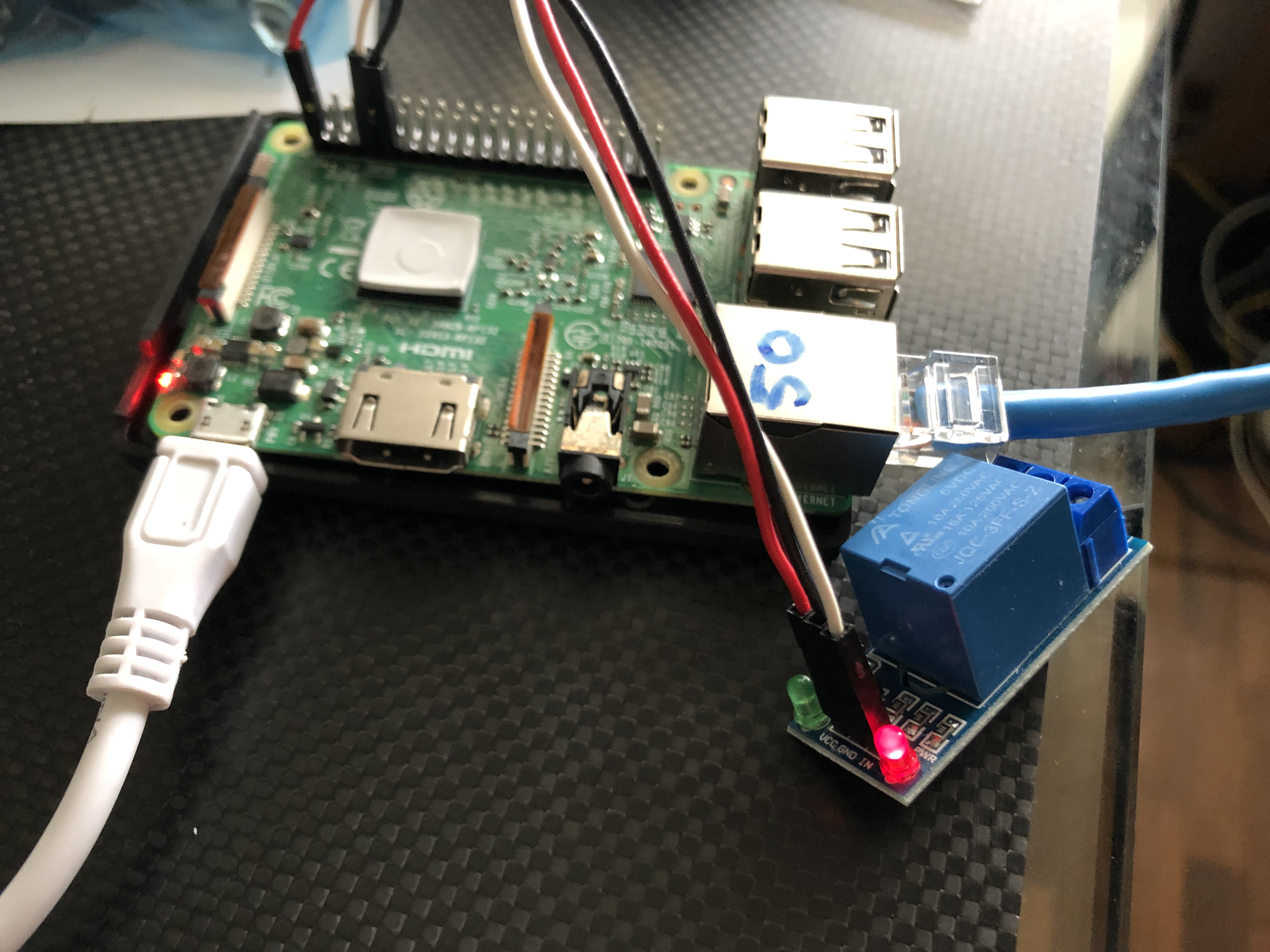
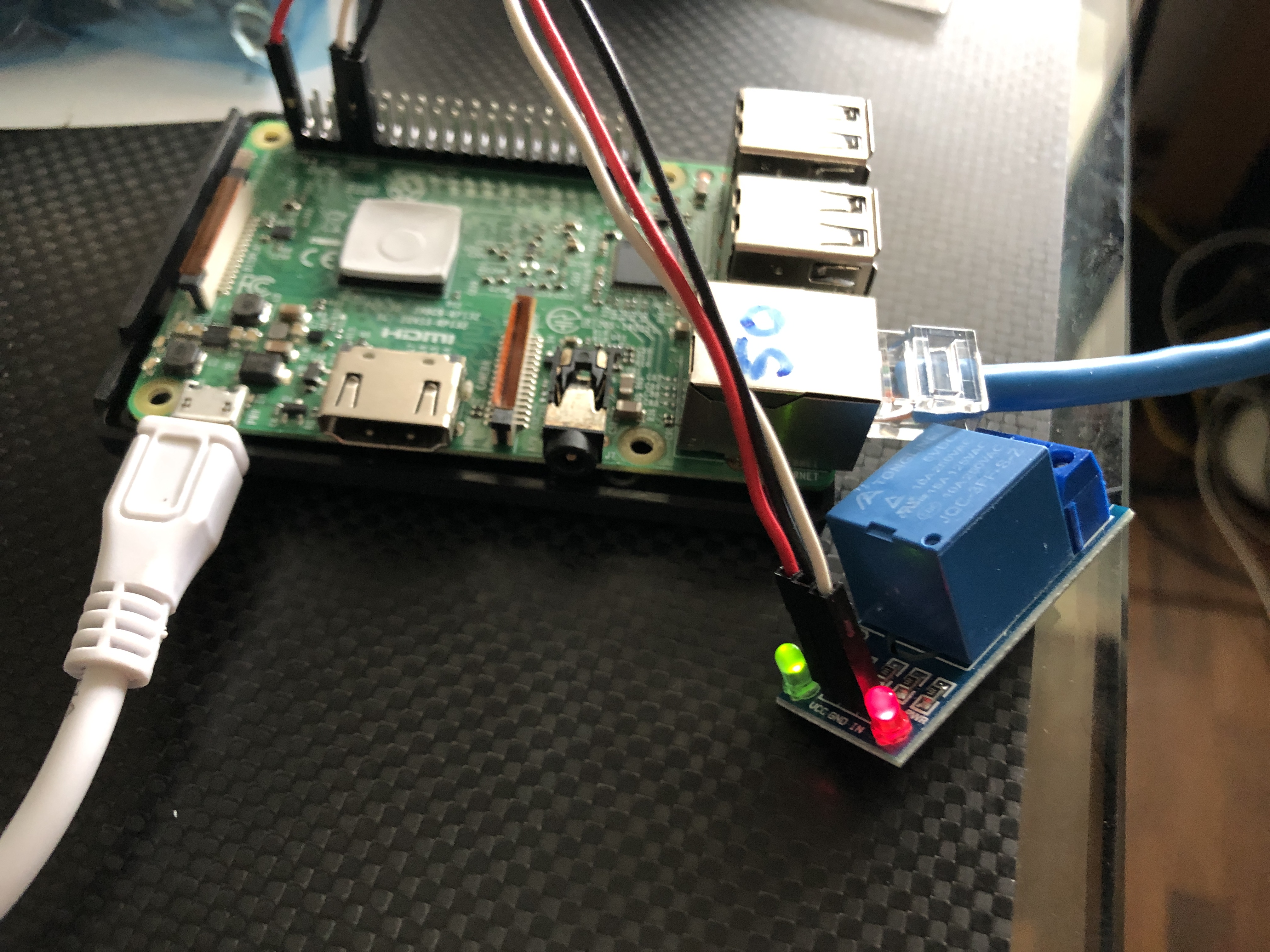
When the software is ready I intend to use a relay board something like this. This would allow you to turn the amp on when the 5V signal is detected and then stay on for however long you want after the signal drops (I’d likely pick ~20min). That way it’s not toggling your amp when you’re changing tracks / albums.
Used in conjunction with a 12V DC power supply of <250ma on the relay side.
My amp (Linn Klout) uses Phono/RCA jacks for trigger and wants to see a 100ohm resistor inline of the + for protection.
Like this:
Has anyone considered using a USB relay? That way we’d be able to avoid conflicts with any installed HATs. My amp accepts 3-30v trigger signals, so it should be possible though I can’t find the voltage available to Pi 3 B+ USB ports I’m guessing it’s 5v