Since the term “uncorrelated DSD quantization/modulation noise/error” keeps coming up in discussions, I thought it would be useful to put this issue to rest and demonstrate there is no such thing. The question we want to answer is: can we design a 1-bit quantizer (or modulator) so that the quantization error of the two-level output signal is not correlated with the continuous input signal? According to the signal theory, the answer is “no”. This is the mathematical proof.
First, a couple of definitions.
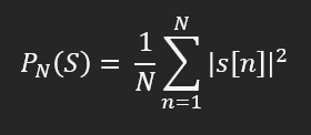
- The average power of a digital signal S over N consecutive samples is defined as:

where:
- N is the number of consecutive samples
- s[n] is the signal’s n-th sample
That is, the average power over N samples is the average of the squared magnitude of those samples. To find the total power of a signal, all we need to do is take more and more samples (i.e. increase N) so that we cover more and more of the time domain and compute the limit of the above formula when N goes to infinity. If our digital signals are well-behaved and have a finite Fourier transform, then, according to Parseval, the average power will converge, so the total power is well-defined.
For a 1-bit signal, there are only two possible sample values, +1 and -1, so no matter now many samples we take, the average power - and thus the total power - is always 1.
- The quantization error of a signal that undergoes quantization is define as:
E = Q - C,
where:
- C is the continuous signal that enters the quantizer
- Q is the discrete output signal of the quantizer
We can rewrite that as:
Q = C + E
That is, the output of the quantizer is the original continuous signal plus the quantization error.
Before getting into the proof, we need one theorem:
Given two uncorrelated signals A and B, the power of the sum of those signals is the sum of the individual signal powers. That is:
P(A + B) = P(A) + P(B)
To demonstrate that no 1-bit (two-level) quantization/modulation can produce uncorrelated errors, I will use reductio ad absurdum, or proof by contradiction. So, let’s assume that:
We can design a modulator that takes the continuous signal C and produces the output Q so that the error E is uncorrelated with C.
Then, according to the two formulas above:
P(Q) = P(C + E) = P(C) + P(E)
Since Q is a two-level signal, its power is always 1, so we can write:
1 = P(C) + P(E)
P(E) = 1 - P(C)
The last formula shows a clear correlation between the power of E and the power of C. That contradicts our assumption that E and C are uncorrelated, so the assumption must be incorrect. This concludes the demonstration.
To summarize in less formal terms, if we assume that a modulator completely decouples the quantization noise from the signal, we find that the input signal’s power modulates the quantization error’s power, which is a contradiction. This is inherent to the nature of two-level signals, regardless of what modulator is used.
Don’t get me wrong, I’m not saying that DSD modulators are not useful (e.g. during rendering). Due to noise shaping, the error in the 0 - 20kHz band can be brought well under audibility, even if it’s in theory still correlated with the signal. My point is simply that the phrase “uncorrelated DSD quantization error” is wrong and should not be used.
As usual, comments are most welcome.