As a chronological continuation of my Lumin A1 in 2023 thread, I want to update everybody here on some fun developments.
One: RoonOnly Mode has been a vision for me and I cannot live without the SQ uplift it brings. I only bring the A1 out of that mode to do important FW updates, then right back into RoonOnly mode.
Two: I have found that I tend to prefer straight PCM from Roon and not upsampling to DSD64. I know the Wolfson DAC’s are better suited to native DSD, but this is a slight personal preference I have developed so far. Subject to change.
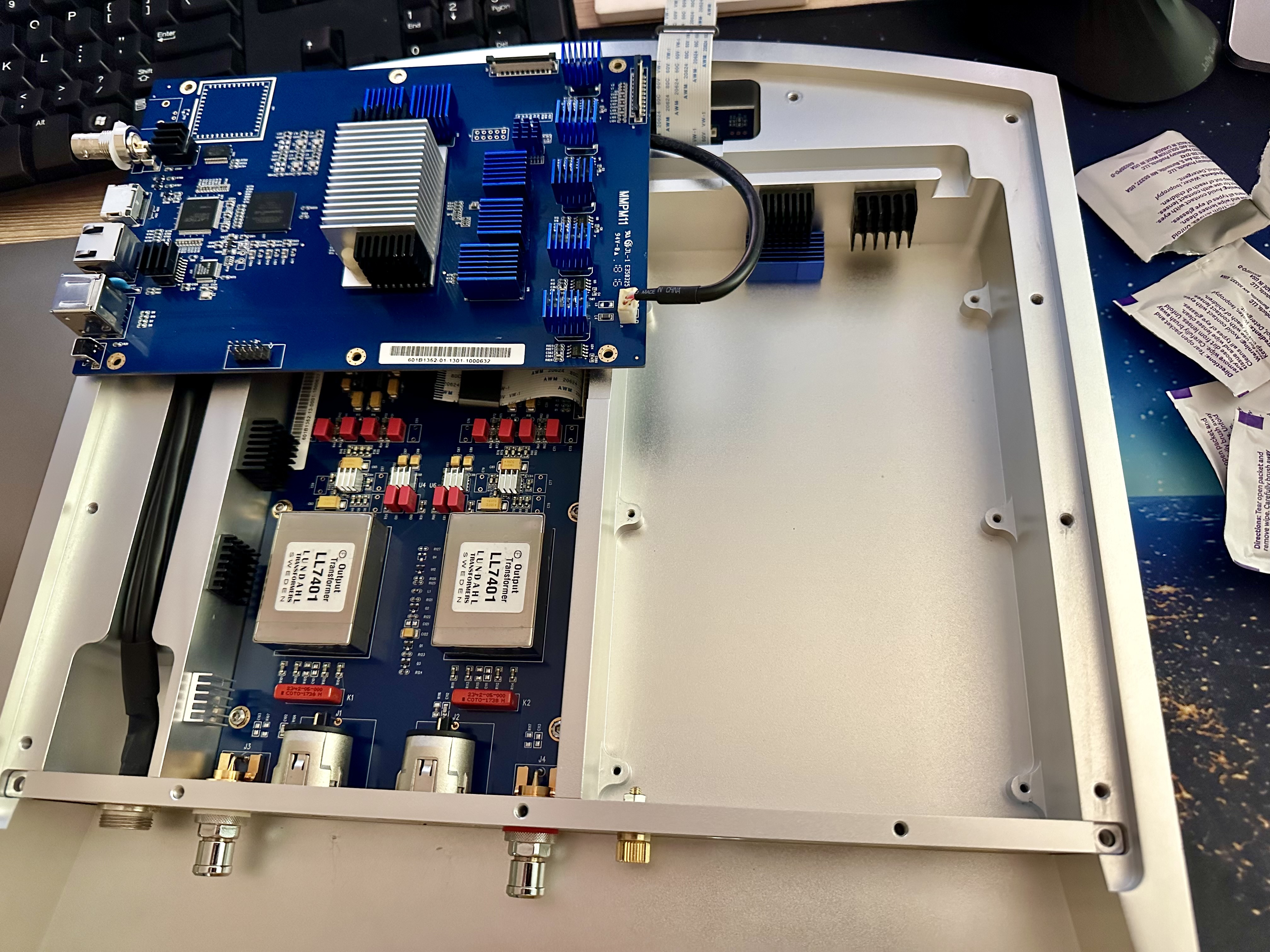
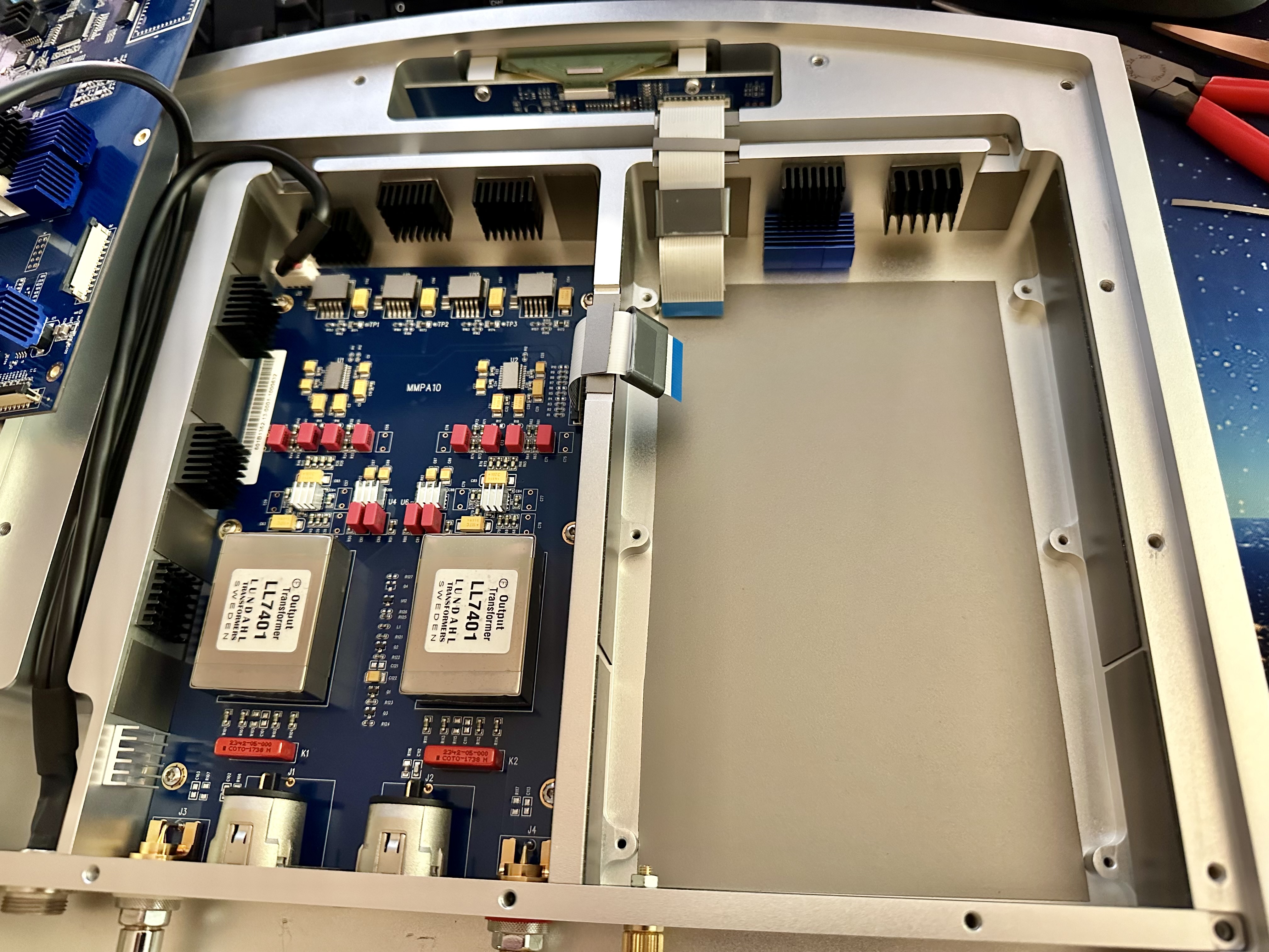
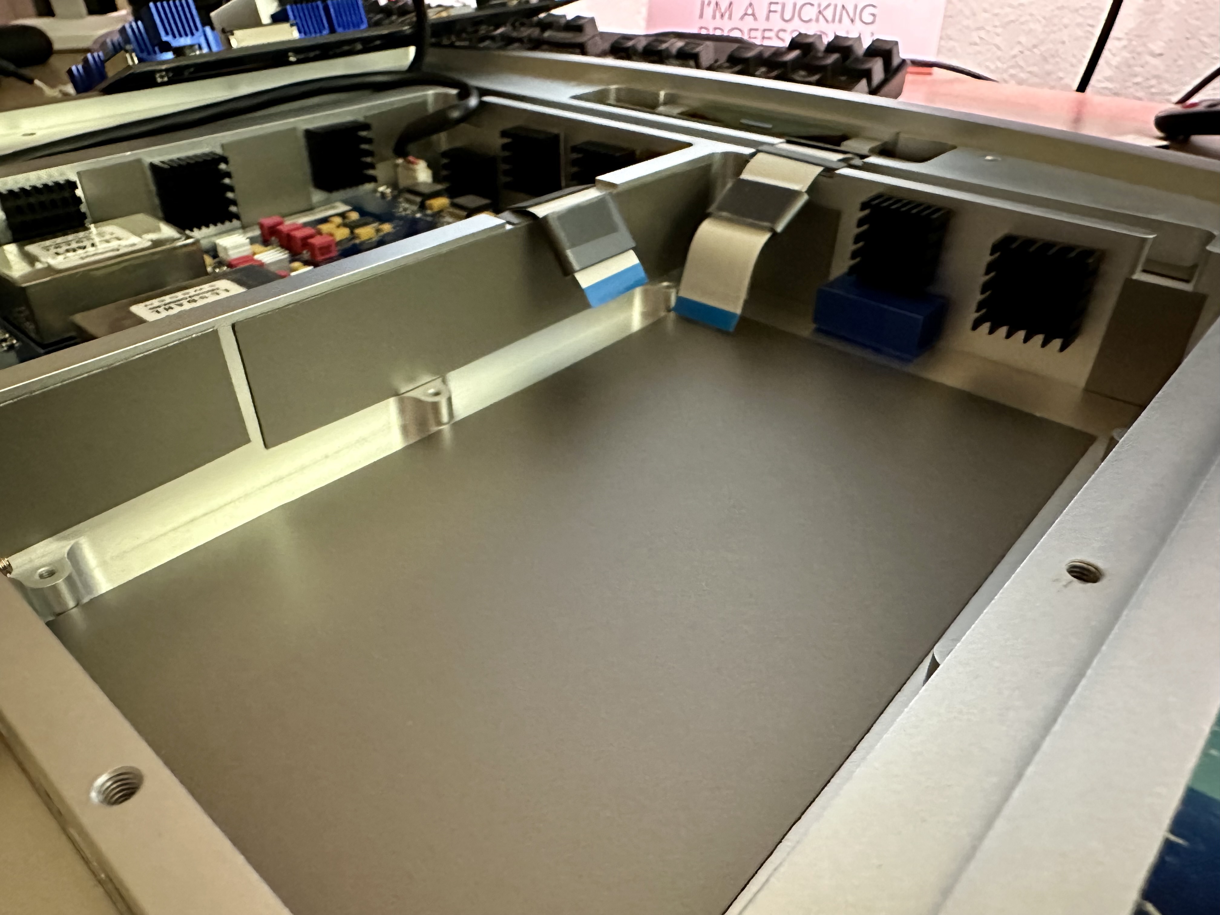
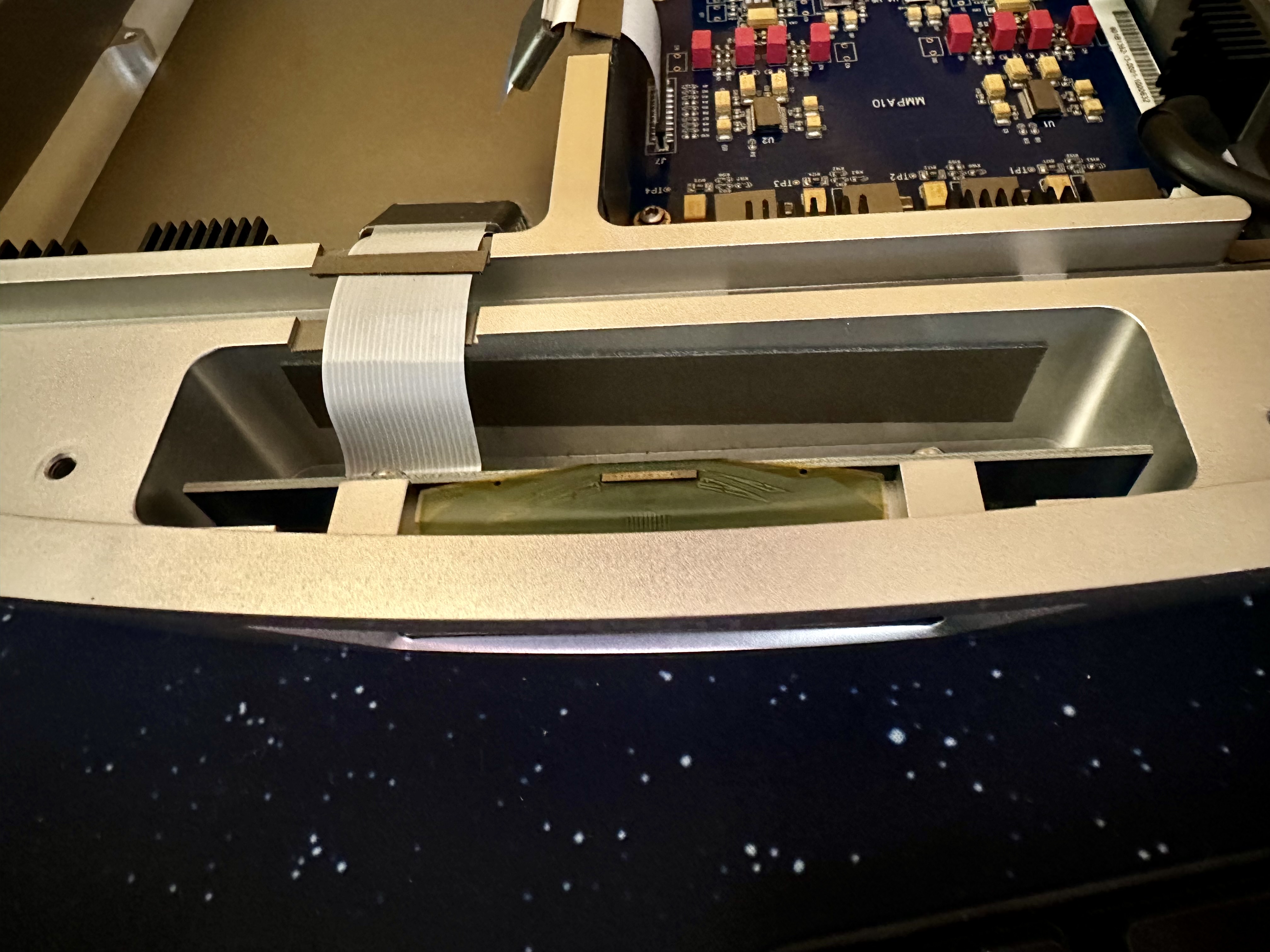
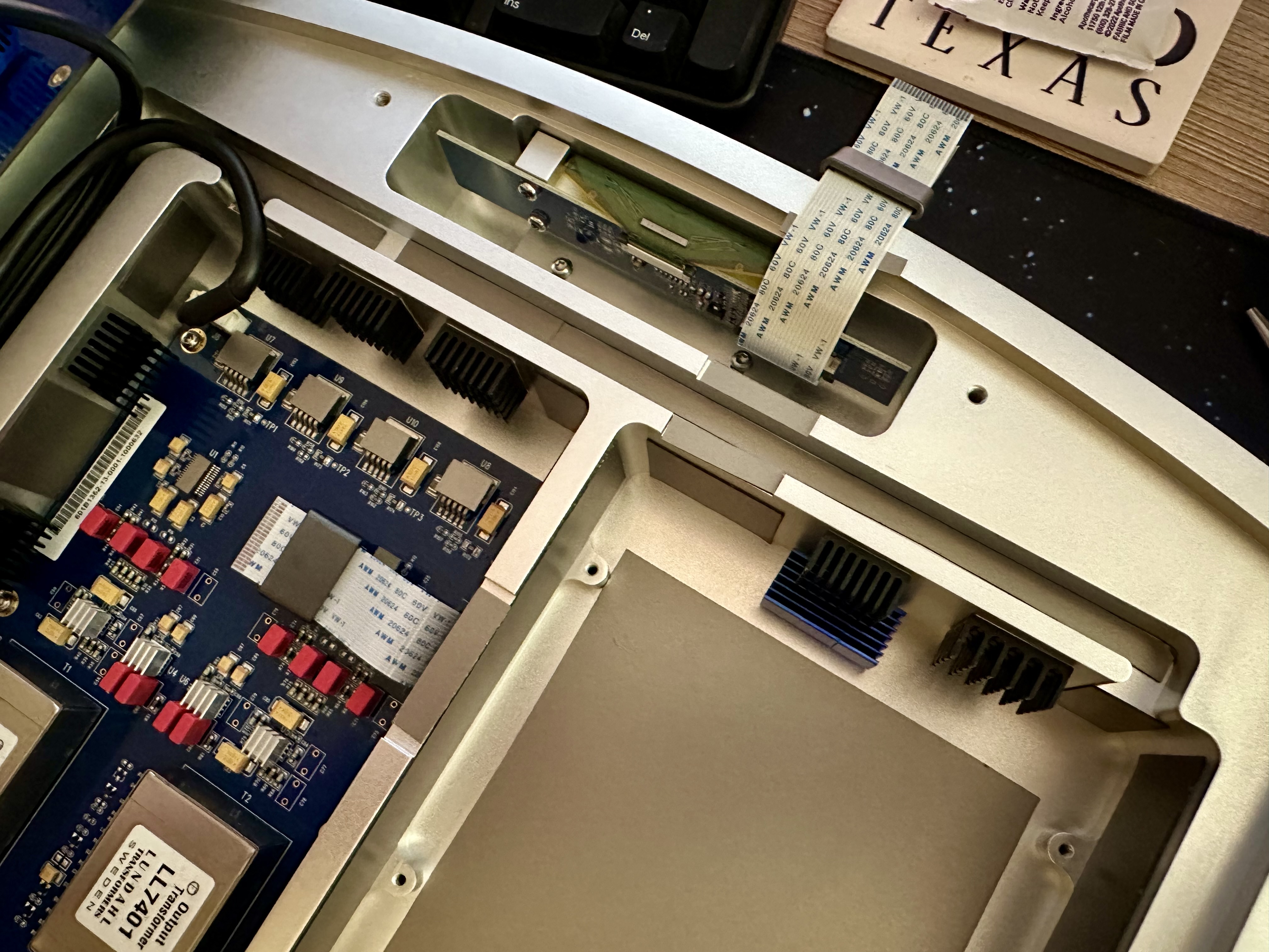
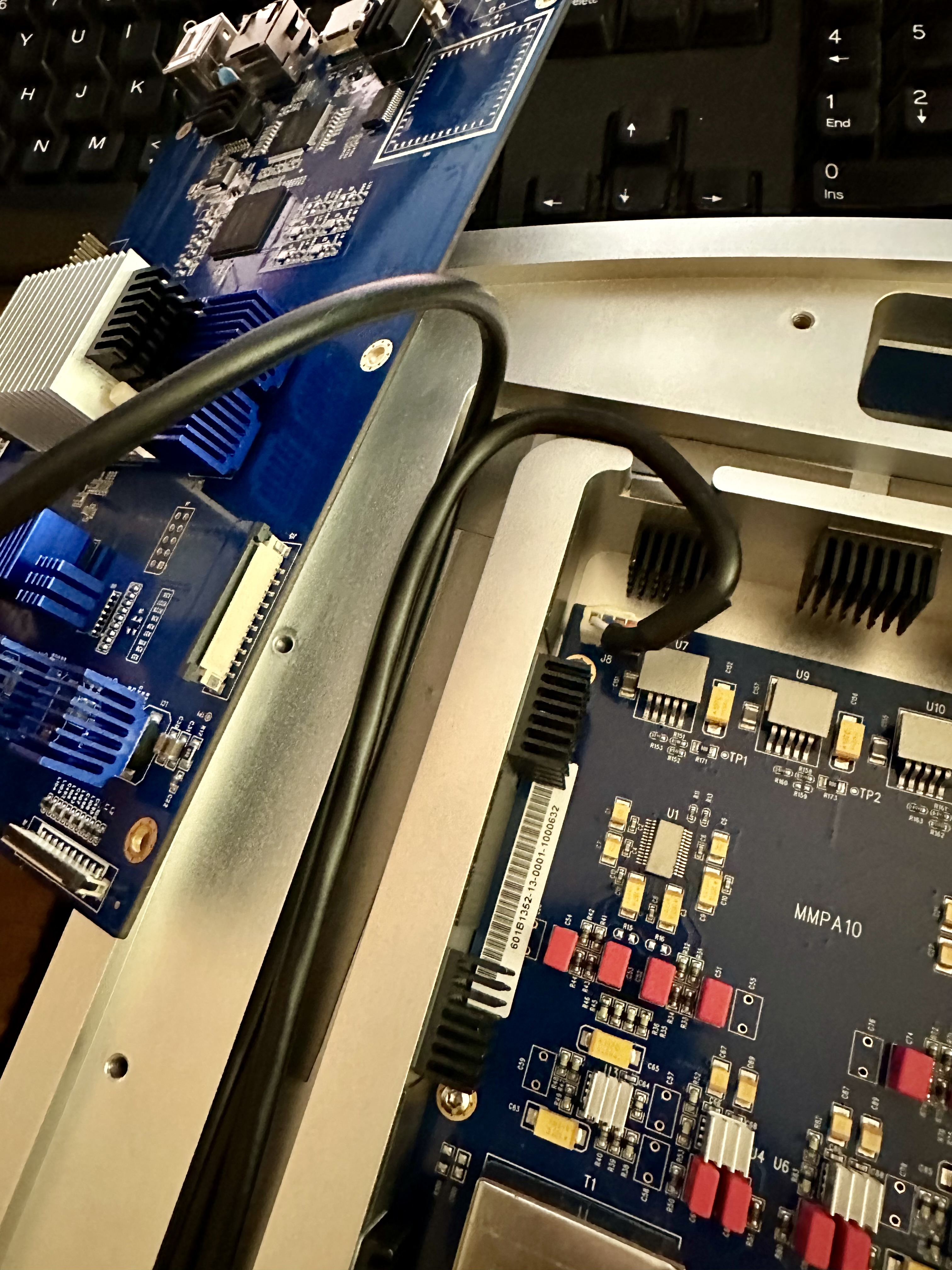
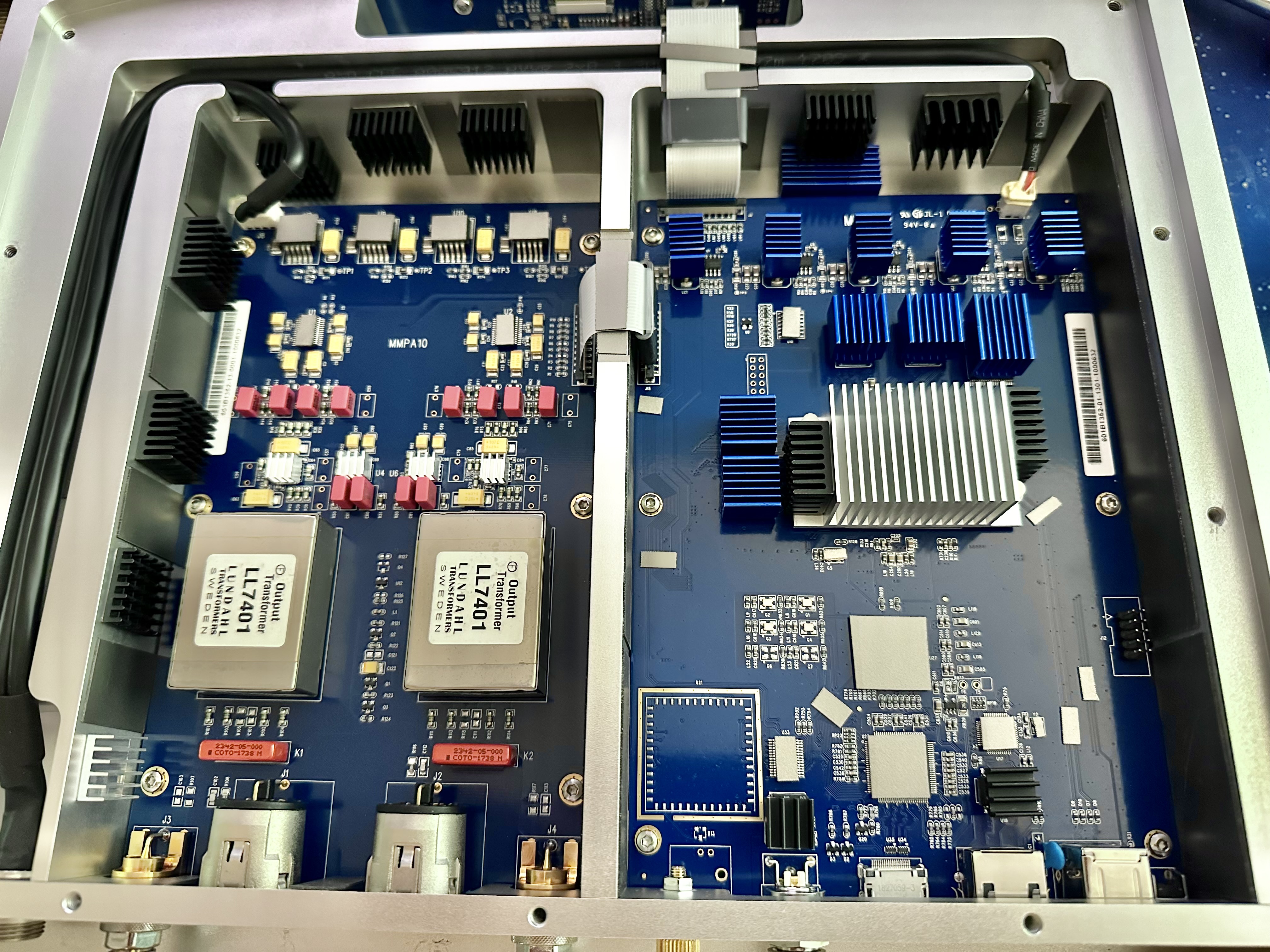
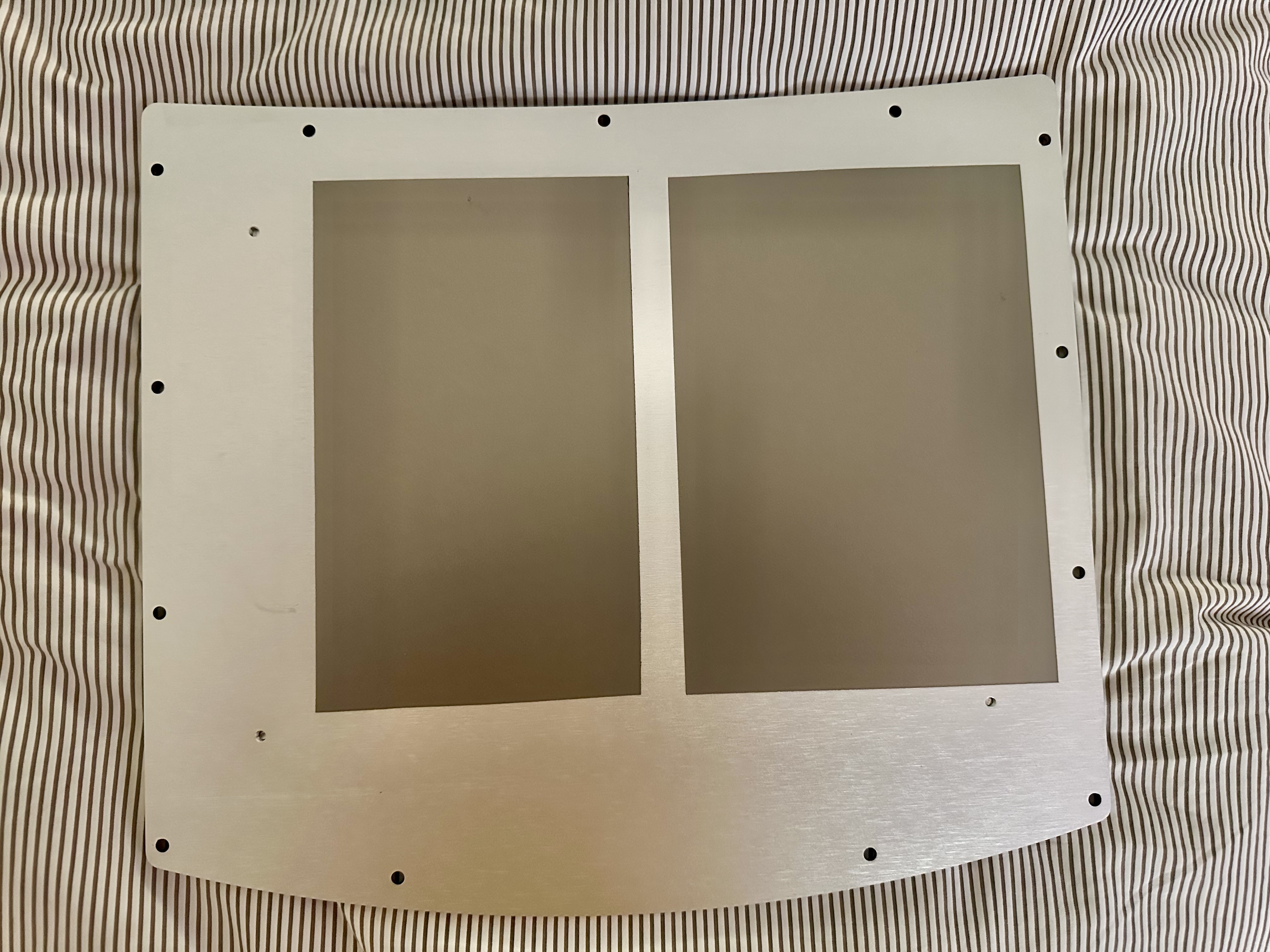
Three: I have recently added some 3M AB7050HF EMC (RFI/EMI absorber) to the A1 and select chips on the boards. I’ll include images in this post (and the next, if necessary) to show. This modification was triggered after I made the “Chord Qutest RFI mod” as documented on other forums. This is where one applies (in the original case 3M AB5030 & 5050) RFI EMI absorber to the inside of the Qutest case, the Xylinx FPGA, the USB XMOS chip, and a few others. I did that with the much more effective AB7050HF and, WHOA. It was an obvious step change in performance in every area. Far more refined in mids and treble, better leading-edge transients, enhanced depth/width/height of SS, more bass resolution, better downward dynamic range (decays/reverb tails), etc. HUGE win. So I began a deep dive on FPGA’s, which bled over into any chip with meaningful processing power. RFI and EMI that is internally generated by these processor chips is a common problem in modern electronics. RFI is directly radiated by the FPGA’s/CPU’s themselves (the actual silicon), it is also carried on the surfaces/traces of boards and of metal cases, transmitted along remote/connector cables, etc.
After that revelatory change on the Qutest, I decided to apply the same mitigation measures to the Lumin A1. I’m sure glad I did.
I basically used my new knowledge from the Qutest mod to enhance the same design concepts that Lumin took great care to implement; i.e. physical isolation of the digital and analog sections. A friend who does engineering for Space and space-adjacent projects says that RFI radiated from FPGA’s and SoC’s can basically “ping pong” around inside of an enclosure, generating and radiating RFI/EMI from 1Mhz to well past 5Ghz, depending on the chip, attached traces, implementation, operating frequency of the chip (higher/faster is apparently worse for RFI), case construction etc. Hence why I placed it above and below the digital board. It can also run across the surface of metal cases in what I can best relay is akin to the skin effect we know of in cables; he went into great depth and it got over my head pretty quickly.
3M AB7050HF page: https://www.3m.com/3M/en_US/p/d/b10223533/