I am engineer working for the company Fink Audio Consulting here in Essen Germany. We use Roon as streaming service for our musics here. I am trying to do some filtering using Roon, so for a try i downloaded the trial version here on my Laptop and using it as the core Below is my question
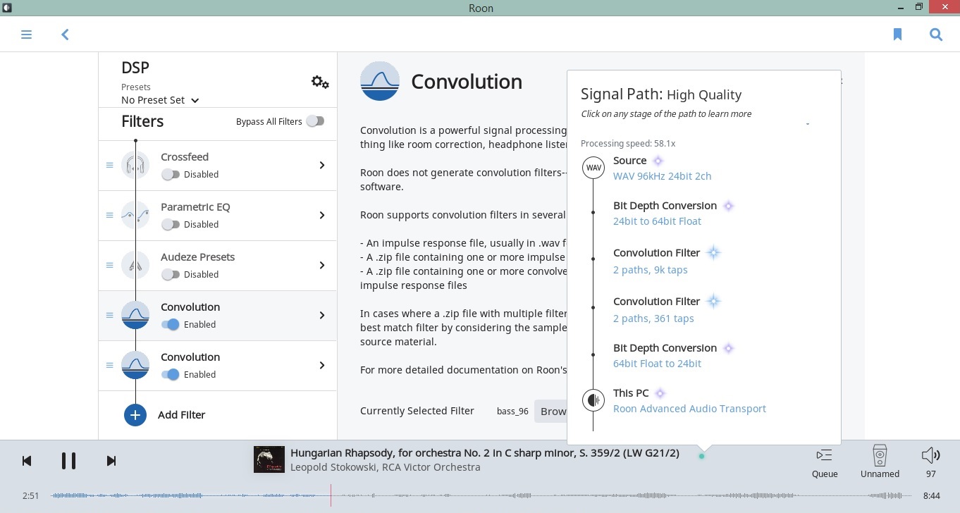
I have two set of filters that i want to use for convolution. So basically i added two convolution filters in the DSP and this is how it looks. Does everything look ok??
What does the usage look like? Does it mean that i am using almost 60 % of my laptop resources?
Hi. Interesting: I’ve never seen two convolution filters used side by side (or one after the other). What’s the purpose of the first and second filter?
Regarding the “Processing speed”: It’s not a percentage, AFAIK. The more CPU is used, the lower the number gets. Usually you are safe with above 5.0 x, I notice dropouts when going below 3.0 x. You are far away from that. Plenty of CPU “headroom”. What’s your core running on?
Thanks for the quick reply. It is actually some psycho acoustic filtering that we are trying on. More details i can give you later, when everything works. As i said my core is now my laptop with core i5 second generation and 8 gb ram, but the actual core (where the music in our company runs), where this will run is on a different pc. Did not want destroy a completely running system, so just getting familiar with Roon on my laptop with a trial license.
Just trying to get my head around the DSD signals right now. I understood so far that Roon can convolve the DSD files, but how and what goes on is still not clear to me.
We still have to do listening test and measurements with this filters in Roon.
An i5 should powerful enough to do down/upsampling and apply at least one convolution filter. Just check the “processing speed” number, again, everything above 5 is OK.
You can create, store and edit various DSP settings in Roon, so if something doesn’t work, just use another saved setting.
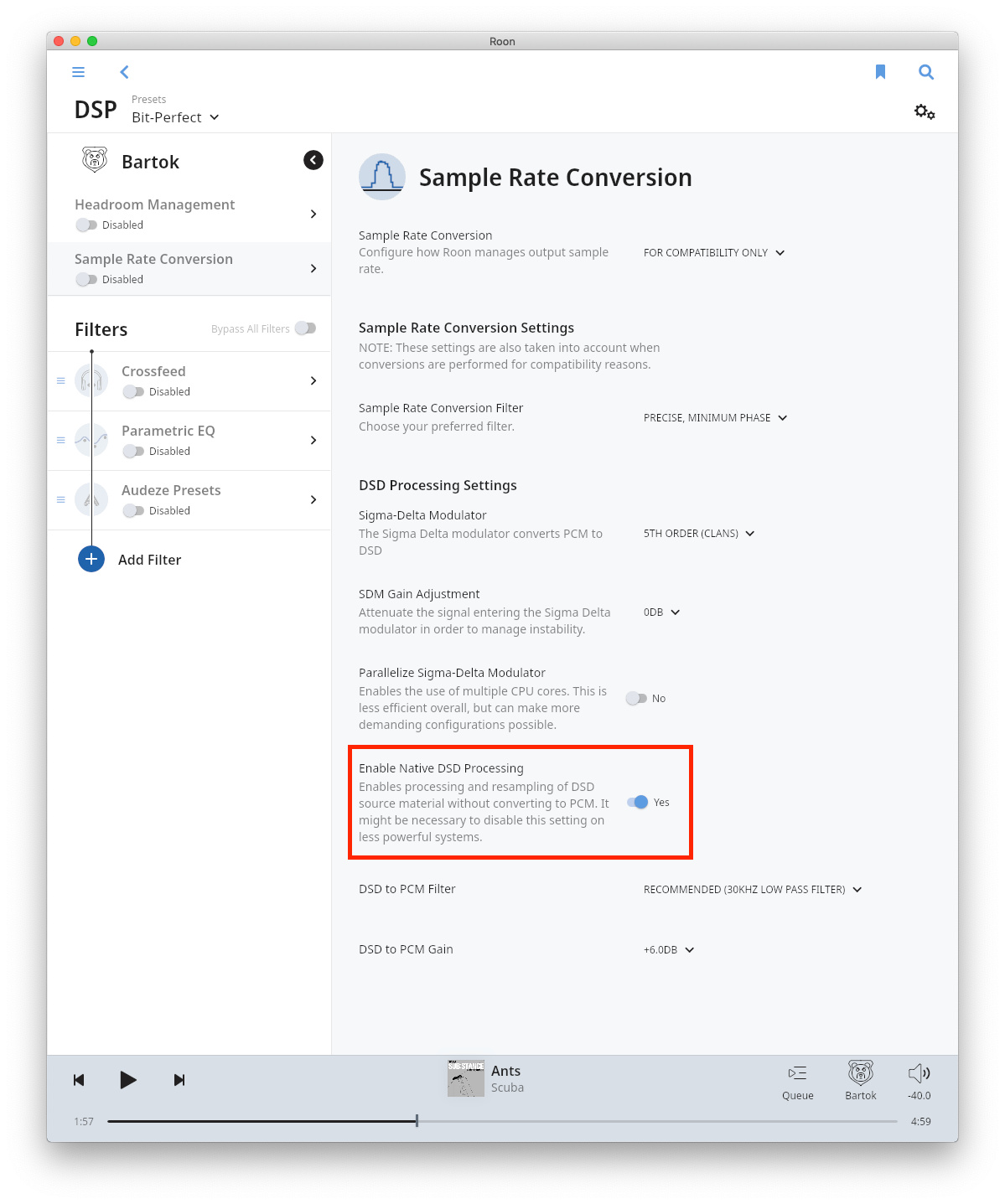
In your screenshot you are using a PCM file, not a DSD file, bit that’s what you want to process? Then maybe this is of help: “…using convolution with DSD is possible but you have to enable DSD processing in the Roon’s DSP Settings under Sample Rate Conversion .” You probably already found this, but I’ll post it anyway: Convolution documentation and Convolver Config File Documentation.
You cant apply DSP to native DSD. Roon will decode it to max PCM first then apply convolution and then change it back to DSD before output. It’s extremely heavy on CPU though.
Thanks Philipp_Schaefer and CrystalGipsy for your answers. Its been really nice to get so quick answers and ideas where to look at
Yes that’s what I also thought about DSD that it will be converted to PCM and then back to DSD. we have to see if our core can handle this. But our core is only running Roon so i guess it should not be a problem. Will post an update and more details as soon as I have it running and some results.
If the processing speed works anything like my DAW, then it is an indicator of how long it takes to process each buffer of audio data relative to the maximum time it can be allowed to take before glitches start and is not a direct indicator of CPU use but is a good indicator of the system load taking all system resource use into consideration.
So assuming the above, 60x means it is processing the audio 60x faster than it absolutely must. In my DAW this is converted into a reciprocal %age, where 100% is the slowest it can operate to preserve audio, and 60x would be 1.666%.
I am facing another problem with my convolution filters. Just to test how it works, i made an Lowpass filter around 100 Hz, so the results are obvious if its working or not. If i generate the filter in REW, export the impulse response and put it to Roon it works. But i generate my filters in MATLAB, does anyone have an idea how to properly get the impulse response out from MATLAB as a wav file?
what I did so far was, create the filter in MATLAB, get the impulse response of the filter and save it as a wav file. But this does not seem work really.
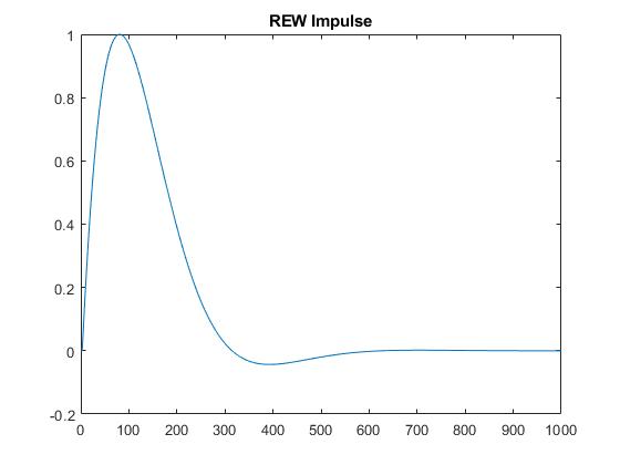
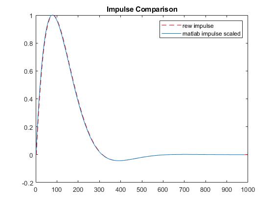
Thanks, meanwhile I found out something. I generated a second order Highpass filter at 100 Hz from REW and exported the impulse response as a wav file, this works nicely on Roon. Then imported this wav file to MATLAB, read in the data and plotted the impulse response.
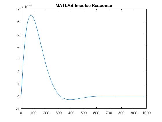
Then i generated a second order butterworth filter in MATLAB and looked at the impulse response, this looks same as the REW one, except there is a scaling difference. The magnitude is lower, and this does not work on Roon, if I save this as a wav file.
The maxium value from the REW impulse response was 1, then i scaled my MATLAB impulse response also have a maximum value of 1, now when i save this scaled impulse response as wav file and put it on Roon, it works.
I am really confused what is going on here. Could you please clarify.
You wrote that the filter ‘doesn’t work’. What exactly do you mean by that, is it :
The software throws an error,
Or, you don’t hear any audio through the filter, or,
Perhaps something else ?
I suspect that you simply don’t hear anything. Judging from your screenshot, there is a pretty severe attenuation in your chain, someway. The ‘gain’ is approx. 0.0065, or a reduction by a factor of 154. That would explain why you don’t hear much . Perhaps you do hear something, if you apply extreme gain somewhere else ?
Then, the next step would be ‘where did that attenuation come from ?’.
I haven’t used matlab for many many years, so I probably can’t be of much help there.
But the factor of 153 does remind me of something. It is quite close to the ratio between 16bit and 24bit max. output.
Is it possible that you are creating a file that hits the 16bit digital ‘ceiling’, but in reality is a 24 bit file that still has plenty headroom left ? Or something similar ?
(This could either be very helpful, or a very silly reply . Not sure what way it will go… hope it can help you out).
The filter you designed in MATLAB is very quiet, so if you pipe audio through it, it will be quiet/silent.
When a convolution filter is applied, the values from the filter are multiplied by the signal then summed at every audio sample. If the filter values are very small, as above, the sum will be very small as well, and the output signal will be very quiet.
One thing to keep in mind is that MATLAB is a tool for all industries/domains and not specific to audio, so you should not necessarily expect that it scales values or generates output according to the usual assumptions of audio processing software. It is a tool that requires you to really have a clear sense of exactly what you want out of it, and does not go out of its way to make things easy.
I had given it another thought this evening, and now pretty sure that I understand.
But I see that @brian already responded (which is great!). He covers most of what I wanted to write.
However, I still have a few things to add to that :
The main problem here, is that you are doing a LOW pass filter. The impulse of such a filter will have very low maximum magnitude.
That’s just science, cannot be avoided.
Thus, rendering the multiplification of ‘audio’ times ‘impulse’, nearly in-audible. I would expect the result in your specific example, to be 44,508dB less loud than the source. (Was that indeed the amount you needed, to align the REW and matlab impulses ?)
That’s very low, and very close to my earlier estimate of 154x, too . Correlates to 168 times.
A different way to write this : I would expect that you can NOT replicate this bad behaviour, if you tried with a HIGHpass filter instead. Is that correct ?
The best suggestion I can give : Find a way to normalize your impulse responses. I am pretty certain that matlab can do this for you. But I’m sorry, it is too long ago, I do not remember how it is done.
By normalizing I mean : take the maximum value in your impulse. Then scale the entire impulse in such a way, that this maximum value becomes the maximum value that your file type can contain. This ensures that your filter gives a unity gain (at most).
By the way : REW does this as well. And that explains perfectly, why your REW filter just ‘works’.
By default, they normalize the impulse.wav when exporting.
But pay attention while exporting : you can also UNselect normalization. If you do so, you’ll get a file with a maximum value that is 44,508dB below full scale (in your specific example). Just as expected… :).
Thanks for your reply and taking time in looking into the issue. Here is my answers to the questions and my understanding of the issue so far
When I mentioned that filter does not work, I meant that i could still hear the audio coming out normally, but no effect of the low pass filter. But when i normalized my Lowpass filter then I could hear the effect of the Lowpass filter.
I understand that if my impulse response is lower like the one I had with the Lowpass filter then I need to normalize it to get the correct audio output. I will try the same thing with a highpass filter now as you mentioned just to make sure.
But what is confusing me, is how do I still hear audio when i don’t normalize my Lowpass filter.
@brian you were right,with the original MATLAB lowpass filter I actually don’t hear anything. I had the same file playing in another zone, that’s what i could hear. So the problem with the convolution filter is solved. My final understanding is if the impulse response of the generated filter is too small then it needs to be normalized.
How do I do convolution on DSD files? I think i need to turn off the Native DSD processing settings? where can I find it?
You may or may not need to disable the setting depending on the sample rate of the DSD content, how powerful your computer is, etc. I would start with “enable native dsd processing” and “parallelize sigma delta modulator” enabled and see how it goes. If your CPU can’t do it, turn off “enable native DSD processing”.
The setting is on the sample rate conversion tab in DSP Engine:
My previous answer was pure ‘logic’; I had not tested anything in real life.
I did make an assumption on what’s happening ‘under the hood’ of Roon, that turns out to be clearly incorrect.
I have now tested, using REW, with and without normalization.
The outcome will probably confuse you even more (sorry about that…). In any case, I don’t understand why your situation is different than mine… :
Each case is an impulse for a 100Hz LPF, 2nd order butterworth, just like your case.
WITH normalisation : Filter does work, but I get severe distortion in my output. I have to provide an additional >>30dB headroom inside Roon (which is not possible), in order to get un-distorted sound.
WITHOUT normalisation : The magnitude in my impulse, is pretty much the same as yours. Meaning : maximum is approx. 44dB below full scale.
This filter works perfectly fine : sounds like a subwoofer, and is ‘normal’ in amplitude.
Pretty much like you’d expect. No idea why your case is different… Can you perhaps share your non-normalized impulse, so I can check it out ?
Hi,
we are doing some group delay compensation on loudspeakers. We use 2 filters, because we do a combination removing the all pass part of the crossover plus some processing on the bottom end. It might go together in one filter later, but right now, we need to use two in order to listen to different correction strategies.
I have another question about DSD: Yes, we need to make it PCM in order to add the filtering, but why is it not possible to stick with the PCM instead of going back to DSD. Can we fool the system by telling it the D/A cannot do DSD and so we only convert it to PCM?
Thanks for help.
So i looked at your suggested settings for DSD and it definetly helps on our system. thanks for that. I am just trying to understand a bit more better about this two settings
Parallize Sigma-Delta Modulator: then the sigma delta modulator is still working? but uses more cpu core?
Enable Native DSD Processing: Then the signal will be converted to PCM for DSP purpose and then back to DSD for output? and if we turn it off we get only PCM as output?
 . Perhaps you do hear something, if you apply extreme gain somewhere else ?