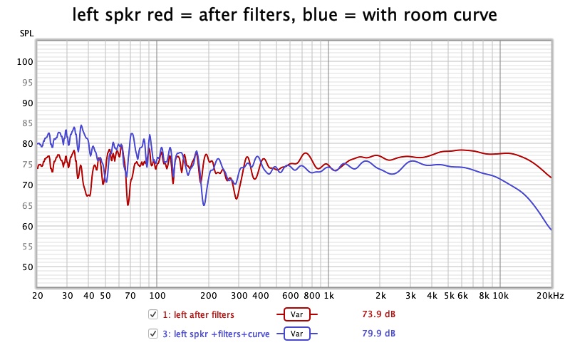
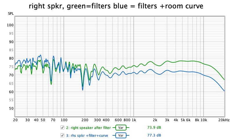
Finally got filters done, set the room curve in roon eq so i can play around a bit with it on the fly. Heres left and right channels with filters only on one trace and filters with curve on the other, just need to decide if im gonna leave it like this or play around treating the room🤔
1 Like
Can this apply to DSD tracks?
Yes though you need quite a lot of power to do higher res dsd. Number of taps is correlated to resolution.
Vs.
1 Like
Mine just makes a big popping noise 
Is my computer just not fast enough?
Also why do you drop your headroom?
You need to match it to your correction EQ requirement. In rew, at the top of the eq window it will tell you how many db it requires. As it’s boosting some frequencies it needs the headroom to avoid clipping.
Popping might be the dac switching between pcm/dsd or is this only when using convolution filters?
It’s only when using the filter and playing dsd. I don’t get any music at all.
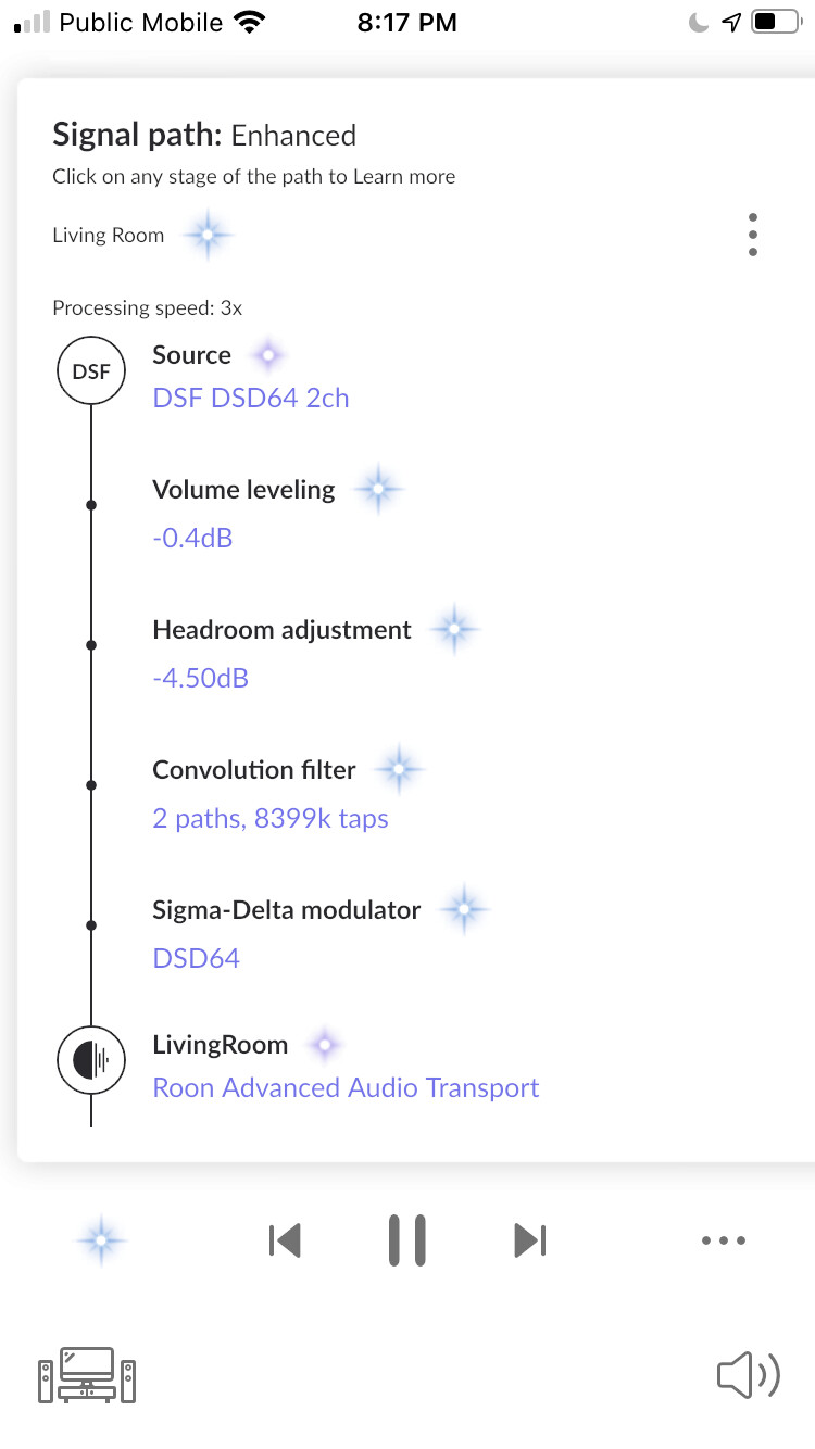
Did you Try DSD64? Does the “Processing Speed: nX” show up? If not or its 0 then yes, you don’t have the grunt to do it.
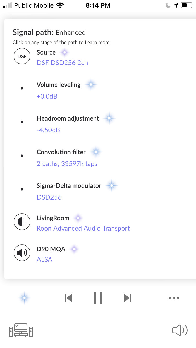
With PCM, I typically see 60-200K taps, as you can see DSD64 is 8399K and DSD256 33597K which only barely works on my setup. Though it used to work, I need to take another stab at my generating my filters as I think if they make fewer changes they will result in a lower number of taps and thus less processing power.
DSP cannot be used on a DSD stream, so Roon will convert it to PCM even if the source is DSD and the output is DSD. However, if you up-sample to DSD than the DSP part will take place before up-sampling, and if output is PCM than DSP will take place after DSD-to-PCM conversion is done.
Its interesting, the Roon docs suggests that they should or used to show this conversion, eg https://help.roonlabs.com/portal/en/kb/articles/conversion-to-pcm#DSD_and_DSP
Although this doesn’t happen for me with DSD/DSP.
I dug a little deeper to figure out my signal path and was correct they you can do DSP on DSD without converting to PCM first. Here’s a quote from Brian explaining it.
We do indeed process DSD without performing a DSD->PCM conversion first. The signal path is reflecting that accurately.
I’m going to explain how it works–keep in mind that there are some subtle technical details here, and some background knowledge is required to understand them fully. Processing DSD isn’t nearly as straightforward as processing PCM. With the exception of a few simple operations, you can’t process it directly in the 1-bit representation. There are more steps involved, but it’s possible to perform those steps in a way that keeps all of the important properties of DSD intact.
First, I’ll explain DSD->PCM conversion, because it helps to understand the other technique in a relative sense.
DSD->PCM conversion starts with a with a DSD signal and produces a signal with two characteristics:
- PCM representation (lower sample rate, wider samples)
- Low noise floor throughout the frequency domain of the PCM format that is as flat as possible.
The first one is obvious–we need a PCM-like representation at the end. The second goal is more subtle–it is saying that the content of the signal must look like a PCM signal. It must be accepted and played properly by PCM equipment. It must be processable by downstream DSP processes that expect to work with PCM data, and so on. It must not cause damage to equipment that’s expecting PCM.
This is accomplished in three steps:
- Start with a DSD stream, and widen from 1 bit-per-sample to 64 bits-per-sample
- Downsample it by 8x (so DSD64 → 352.8kHz, DSD128 → 705.6kHz, etc).
- Apply a low pass “reconstruction filter”. This filter also exists in a DSD DAC, but since we are effectively simulating the DAC, we must simulate that aspect here too, since PCM DACs do not have this filter.
The reconstruction filter removes the noise inherent to the DSD signal before it can reach equipment that might not be prepared to handle it. Most of the energy in a DSD signal lives in this noise (well over 95%), so even though the noise is all at inaudible high frequencies, it’s important to filter it out so that your gear is not asked to turn that energy into loud, high frequency sound.
If you look at a spectrogram of DSD->PCM converted data, it looks like a PCM signal. Depending on the source material, and the sensitivity of your spectrogram, you might see a bit of a very quiet noise floor in the area where the transition band of the noise shaping filter used during mastering crosses over with the transition band of the DSD->PCM low pass filter (30-60kHz for DSD64).
OK, so now that DSD->PCM is explained, lets talk about the case you’re actually interested in–the one where we process and output DSD without converting it to PCM.
This works like this:
- Start with a DSD stream, and widen from 1 bit-per-sample to 64 bits-per-sample
- Apply a low pass filter to remove the bulk of the inherent noise energy from the widened signal.
- Apply processing steps to the wide intermediate format.
- Send the signal through a sigma-delta-modulator to re-render the “wide” 64-bit stream into a 1-bit DSD stream.
The low pass filter (2) in this process might sound like the reconstruction filter we discussed above, but it is very different. It is much more lenient, less steep, and it only attenuates frequencies over 100kHz–and these already have a very poor SNR because of the inherent noise shaping in DSD, so we can be sure that no meaningful information existed there in the first place.
Without the filter, sound quality suffers significantly or the sigma delta modulator risks becoming unstable (i.e. starts outputting horrible sounds that ruin your ears and if you’re unlucky your gear too).
At step (3) the signal is structurally similar to a PCM signal–in that it is comprised of a series of multi-bit samples. However, it does not have content typical of PCM signals and it maintains the DSD sample rate. If you looked at a spectrogram of the intermediate format in (3), it would look just like DSD, except with the bulk of the noise above 100kHz severely attenuated by the low pass filter.
By maintaining the original sample rate through processing, the time-domain characteristics of DSD are maintained. By designing the filter to stay far away from musical content, the frequency-domain characteristics are maintained too.
Sometimes this form of processing, or this intermediate format is referred to as “DSD-Wide”. We didn’t use that term because some people have defined DSD-Wide as an 8 bit intermediate format (whereas we use 64 bits…a luxury of precision afforded to us by running on modern desktop-class CPUs) and I didn’t want to create confusion.
4 Likes
Interesting, so Roon does a conversion to a PCM-alike data stream that is still in essence a wide DSD stream.
Hi @Magnus
thx so much for the interesting writeup
i bought the umik-1 mic and followed your excellent guide until the EQ stage that left me very confused  this is what i get for the left measurement
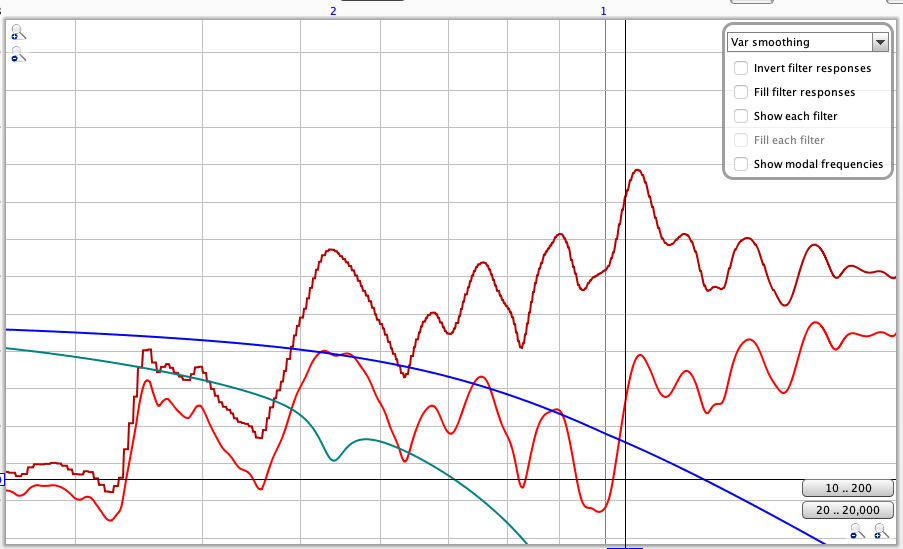
- does this seem reasonable? (the blue line seems to dip and is very different from your example )
2)what do i do from here, you mention i need to correct things but im not sure how
thx alot!
Z
That looks wrong, I think the blue line is from speaker choice (use speaker none). But the measurements themselves looks all over the place, although I can’t see the scales. Maybe a new screenshot with scale 20 - 20Khz and 50dB - 100dB (use the button on top-left with a cross of arrows in it).
haha i knew i didn’t something really wrong
so to be clear again
when i do the test i connect the mic to my mac.
then i also output (the pink noise) from my mac to my speakers (KEF LS50 Wireless II) and then measure as you said from hearing height in my seat (i sit near a desktop with my KEF on the sides). when i measure i hold the mic in hand near the ear and circle around the ear?
is that the correct workflow?
best
Z
Sounds correct, if you measure without playing anything you should see background noise around 30dB or up towards 40dB in an apartment. Then try to get around 75dB with Pink PN noise
ok thx! will try later on when kids go to sleep
Hi again @Magnus
so i tried starting from scratch and again i got to the EQ stage. this is the left speaker current result (with the scale you mentioned above)
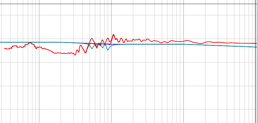
does the graph now makes more sense than before?
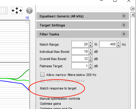
Make manual changes to the result, or try different settings in the “Filter Tasks” side-window, until you are satisfied with the result.
this stage is where im at loss, how do i manually make the changes and what am i aiming for ![]()
thx a lot again, really appreciate your help!
Z
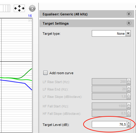
That measurement looks more normal, but you need to show axis values as well, there is an “export as image” button up to the left you can use. But judging from picture and default values, I would guess you should set target to 79 dB and then let REW correct
These steps are described in the guide, step 11