They are complaining about the exact same thing!
2 Likes
The wrong statement in the Mackie blog is…
When a signal reaches the point of clipping, speaker cones do not move, as the clipped signal is essentially a DC signal for the duration that it exceeds the voltage rail boundaries.
This causes all of the power from the amplifier to be used towards heating the voice coils
A DC voltage/current across/through the voice coil effects a static magnetic field opposing the motor’s magnetic field, which will force the diaphragm away from it’s spider-and-surround spring loaded resting position, keeping it at that equilibrium position for as long as it’s present.
Of course, the voice coil is not accelerated any more and “doesn’t move”.
Any current through the voice coil, AC or DC, causes a voltage drop across its series resistance, thus causing power dissipation.
Yes, an AC signal keeps the voice coil moving, effectively cooling it by forcing air through the gap along the coil.
But the real heating power is effected by the added high frequency content!
2 Likes
Many thanks, this is very interesting. One question; is it possible to follow this guide without doing the soundcard calibration with good results?
(I am using a work laptop for rew, and neither asio4all nor equalizer apo were allowed to install).
And also; do you use this correction over the whole frequency range with good results? In my previous corrections with rew I have only used the 25-300hz range (athough this was with more traditional eq-corrections).
Thanks!
Use a USB microphone with calibration file (like UMIK) and export REW’s measurement files to Roon to play from there, and no soundcard calibration is needed.
1 Like
The new Rew introduced wasabi java drivers which are almost as good as asio drivers. Work laptop will probably have java installed so no need for asio4all either.
You don’t normally correct above Schroders (your room transition frequency, usually below 150-200Hz) as you don’t want to correct the speaker but the room. However room effects are still audible for up to 3-4 times that level so some people benefit from correcting up to 600-800 Hz. Justification for correction beyond this level is that many speakers today are designed to impress in the shop listening test and boost upper mid band which causes ear fatigue in the long run. IIR filters will shift phase way too much while trying to correct high frequencies so the compromise is usually not worth the benefits however with FIR filters, you should be comfortable with minor corrections all the way to 20kHz. Just keep in mind that above 5kHz the wave lengths are so short, even little movements of your head will effect the actual frequency response more than the filter so it may not be worth it.
2 Likes
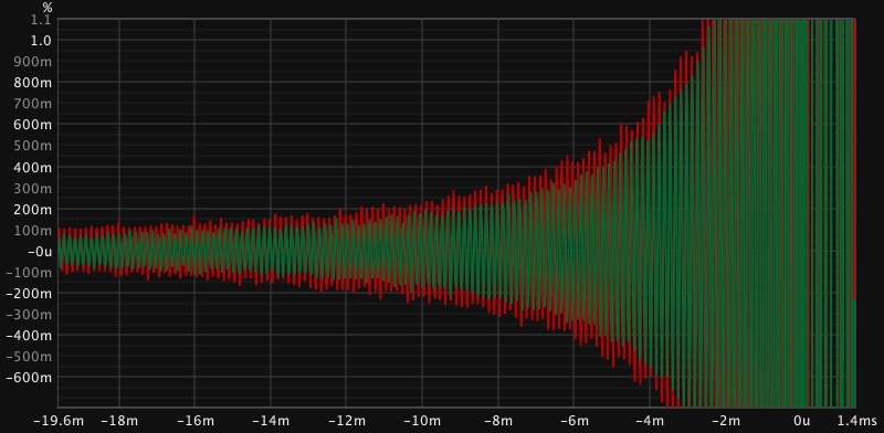
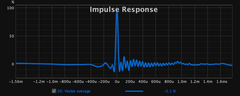
I can’t seem to get an impulse response, I get lots of small waves, it doesn’t make sense, have I recorded it wrong?
That looks like the impulse response of a trace arithmetic division rather than a speaker measurement. I can’t see any useful information on the graph to comment.
Hi Serkan,
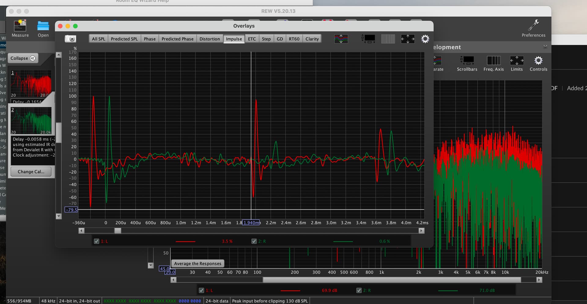
now I am getting 3 impulse responses.
I am running REW 5.20.13 through a Mac mini connected to a Devialet amplifier by HDMI to ATC SCM 19 speakers and my mike is a UMIK 1
Should I try it through windows emulation?
Mac version should work just fine, no need for emulator.
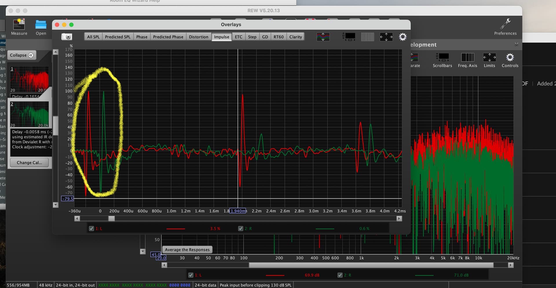
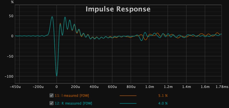
You’ve only 2 impulse responses (left and right - circled in yellow), the other peaks seem to be very strong delayed reflections of the first impulses.
1 Like
EDIT … oops, Serkan beat me, while I was typing my blurb …
I’m not @OCA, but may be able to offer some input as well.
You’re showing responses for two individual measurements - left and right channels, I’d guess in red and green.
The red trace reveals a very strong reflection ~2.2ms after the initial impulse, equaling a pathlength difference of ~29", so there’s got to be a reflecting surface quite close to that speaker.
The green trace’s reflection with about the same distance is better attenuated.
Both traces show another reflection with a pathlength difference of ~51".
Since these are rather large in amplitude and close to the initial impulses, I’d highly recommend trying to optimize speaker positioning and maybe introduce acoustic treatment to ameliorate them before attempting to correct with DSP.
1 Like
thanks for the info v help full yes the back wall is close to the speaker. I only have a small room of about 4 m x 5m so placing the speakers is difficult and will never be optimal. But I enjoy these technical challenges to /tune the sound. I am almost at the end of your video with the impulse correction response, I found the video easier to follow than the pdf. The thing that I was not sure about was smoothing in the eq window, i.e. do we use 1/48 smoothing there?
/thanks for the tutorial very good.
here is my impulse correction:
if the left speaker has a Delay -0.0144 ms (-5.0 mm, -0.19 in)
and the right speaker has a Delay 0.0403 ms (14 mm, 0.54 in)
does that mean we should input a distance of 19mm in Roon?
like this?
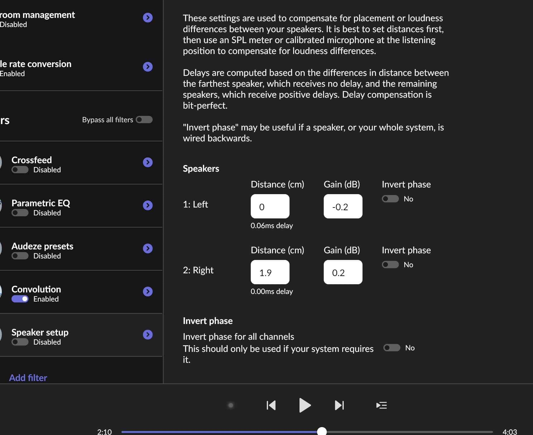
Yes, correct👍
1 Like
Seems to have really improved central image especially with vocals. Might try rephase next…
Well done!
1 Like
How do you do this?
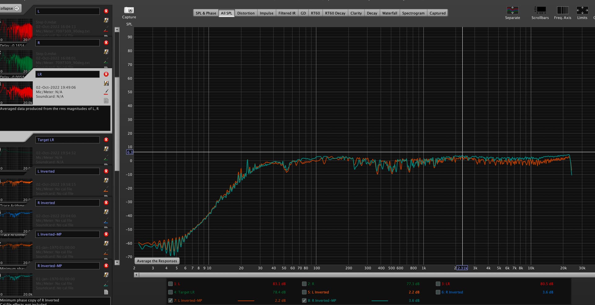
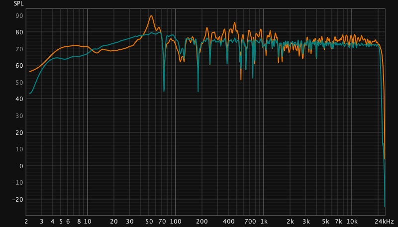
My corrected system measured from Roon using measurement sweep:
left channel:
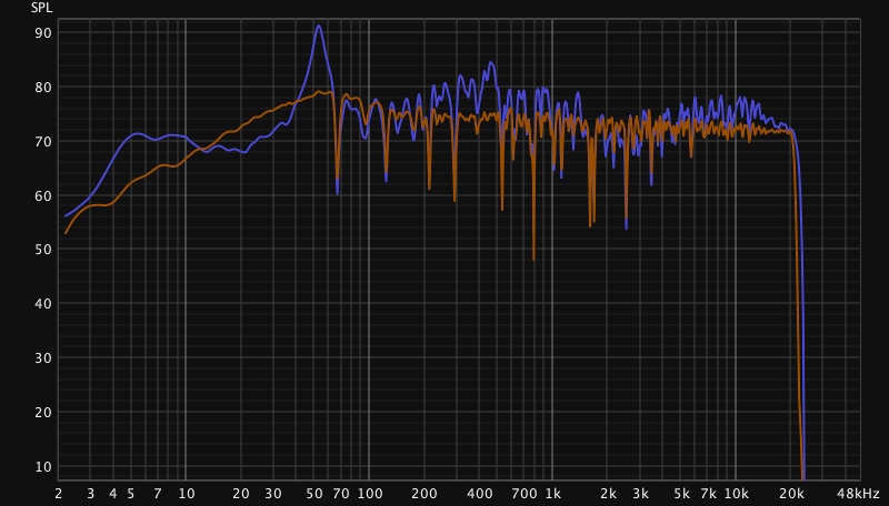
right channel:
Impulse:
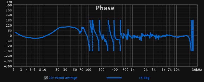
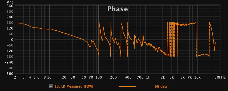
Phase:
there didn’t seem to be any phase distortion at the crossover of 2500hz. I can’t seem to correct for the phase inversions below 1khz any ideas?
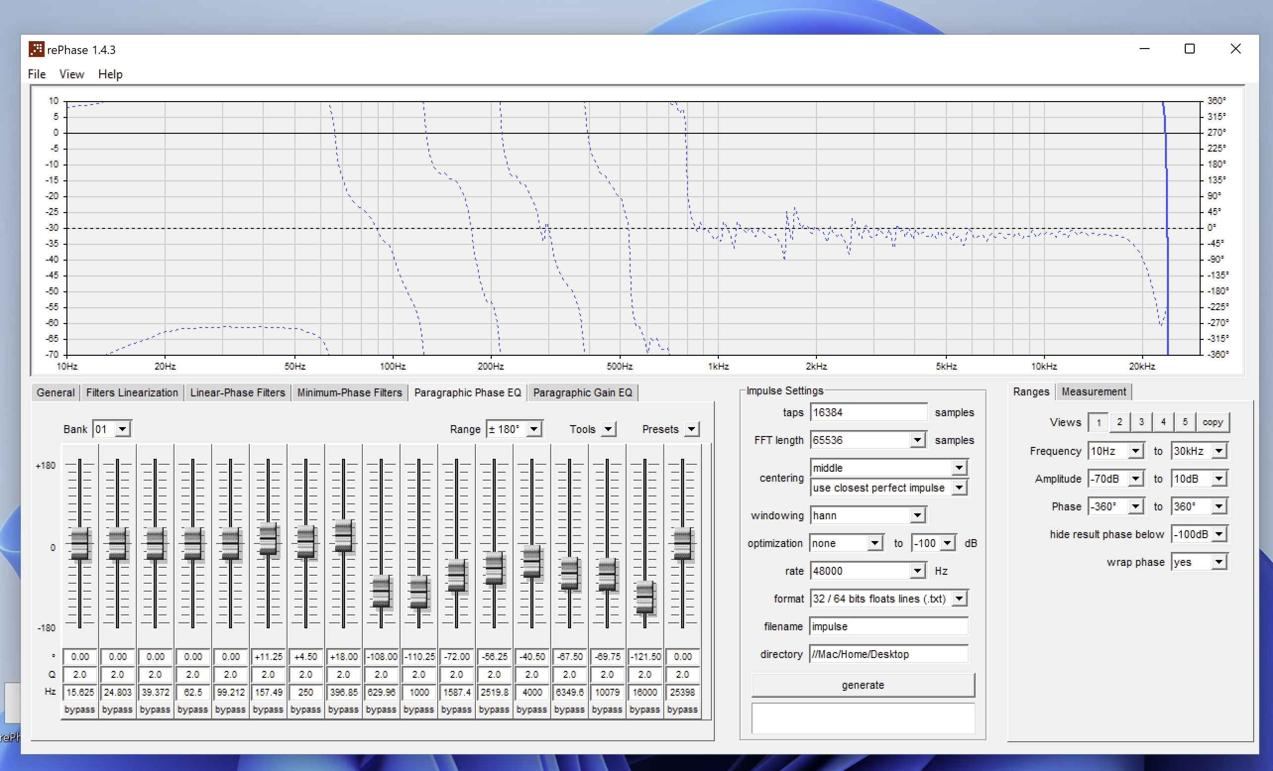
I applied rephase:
this was my phase for vector average response:
and without rephase but with Corrected Minimum Phase
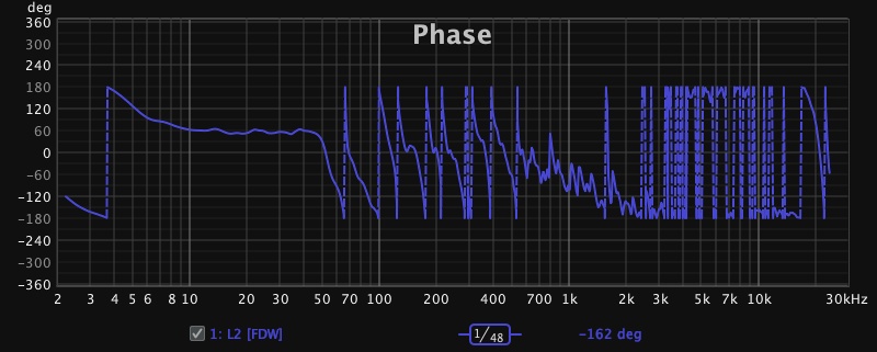
and no system correction for phase:
The crossover is at 2500hz with 2nd order 12db slope
corrected impulse response:
The correction seems to work as intended, does it sound good?
1 Like
You need to apply that 12 dB filter linearization at 2500Hz, it doesn’t look like it’s done to L2 in the graph.