DIY Speaker Build - Troels Gravesen's Poor Man's Stradivari

I posted some photos on another thread earlier this week, but thought I should do a proper build thread.

Nearly all of my speakers in the last 15 years or so have been DIY builds. There is a good number of very talented speaker designers around, and it’s easy to find good designs and/or kits online. I’ve been enjoying a pair of sealed Zaph Audio ZRTs for the last couple of years.

If you’re competent at woodworking and can wield a soldering iron, a good DIY build can bring “high-end” performance at mid-fi pricing.

The cabinet is a wide baffle design. Besides the unique sonic signature, the wide baffle requires less attenuation of the mid and tweeter compared to the bass driver, which improves efficiency. Efficiency of this design is ~90dB.

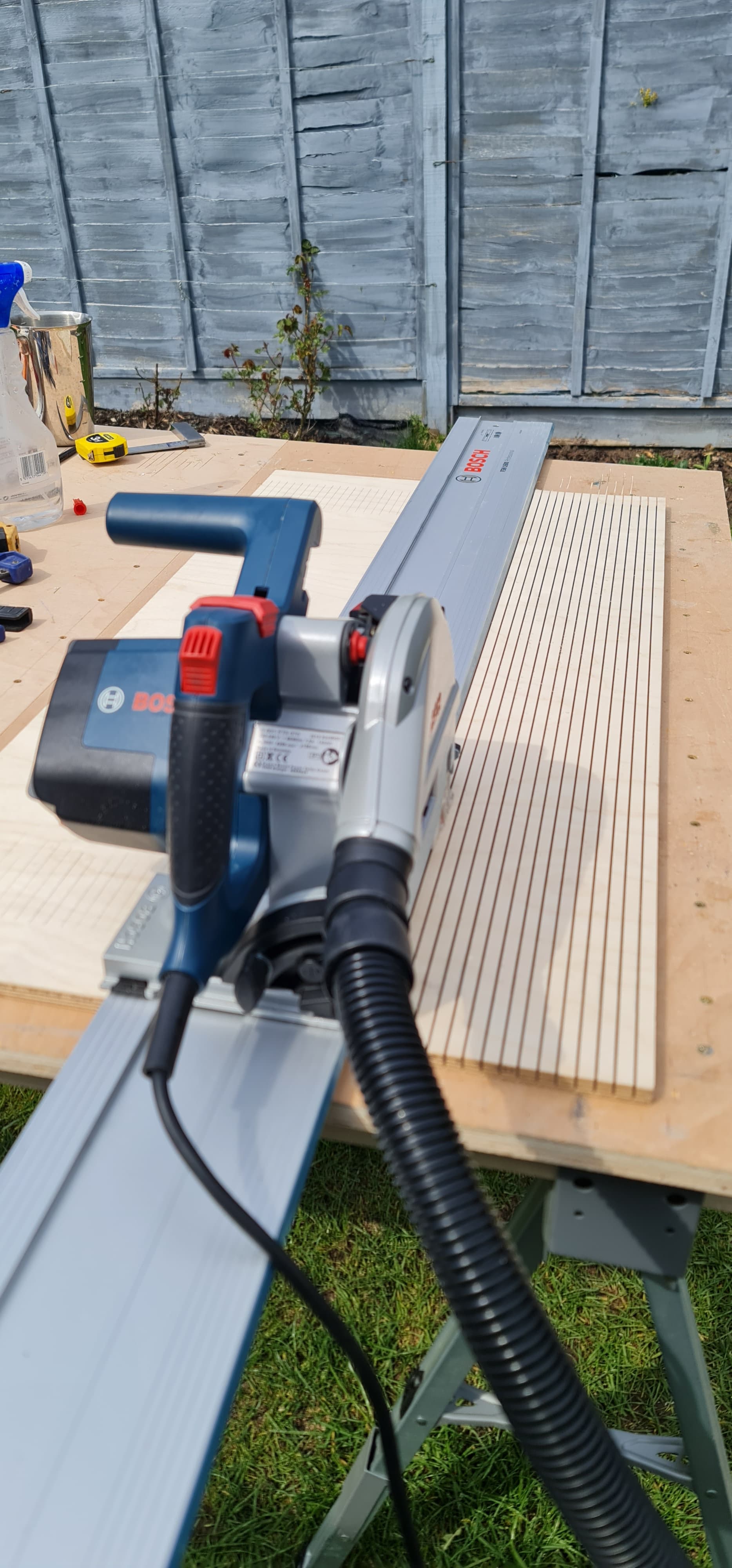
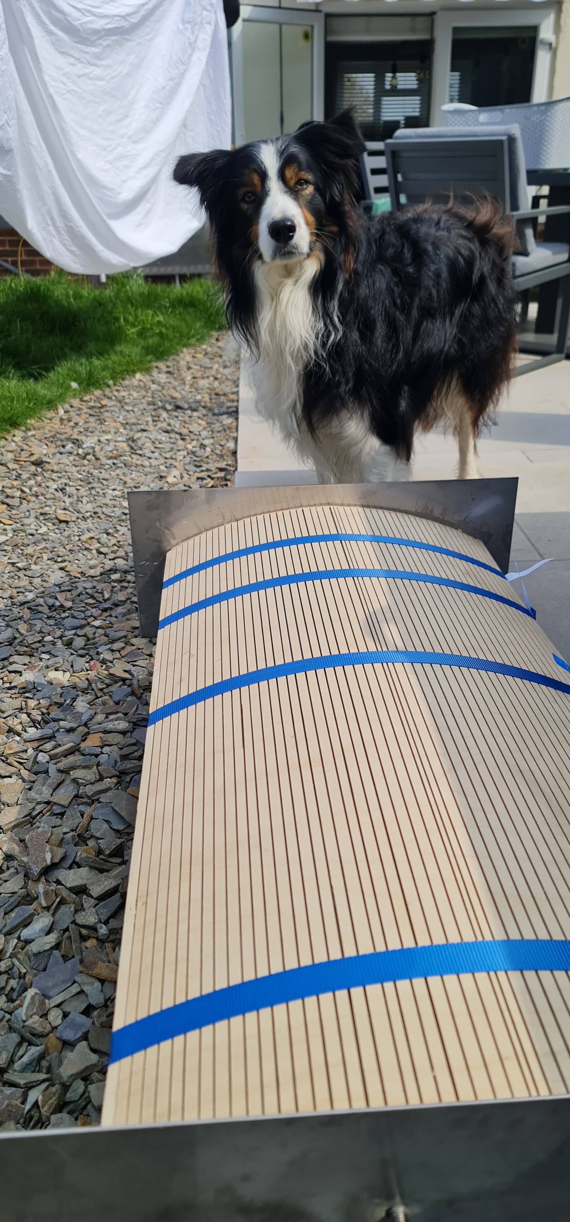
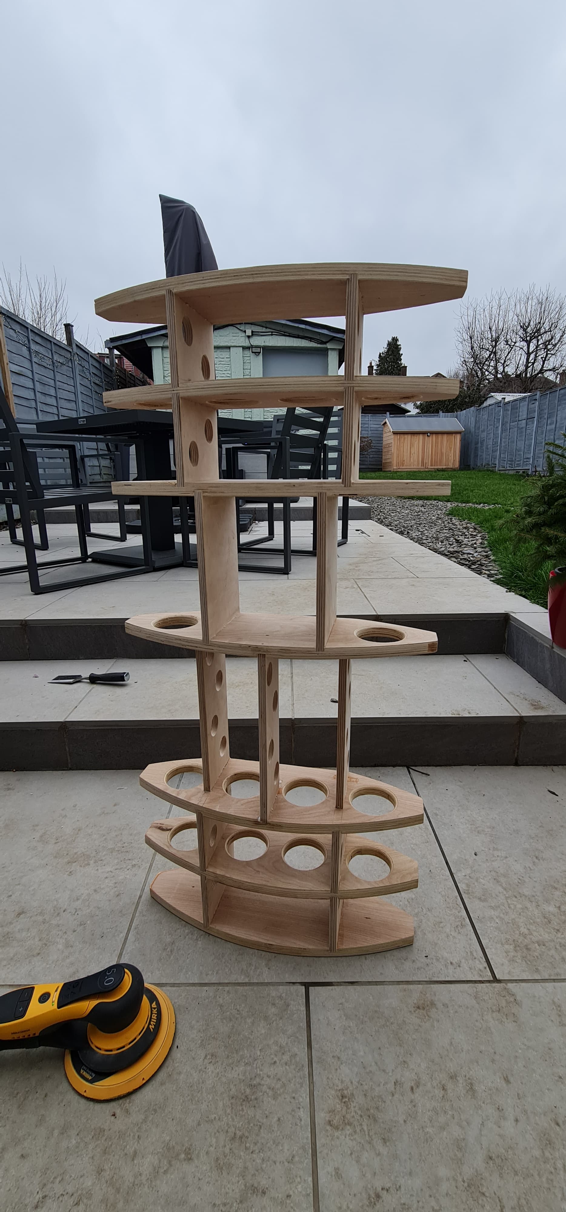
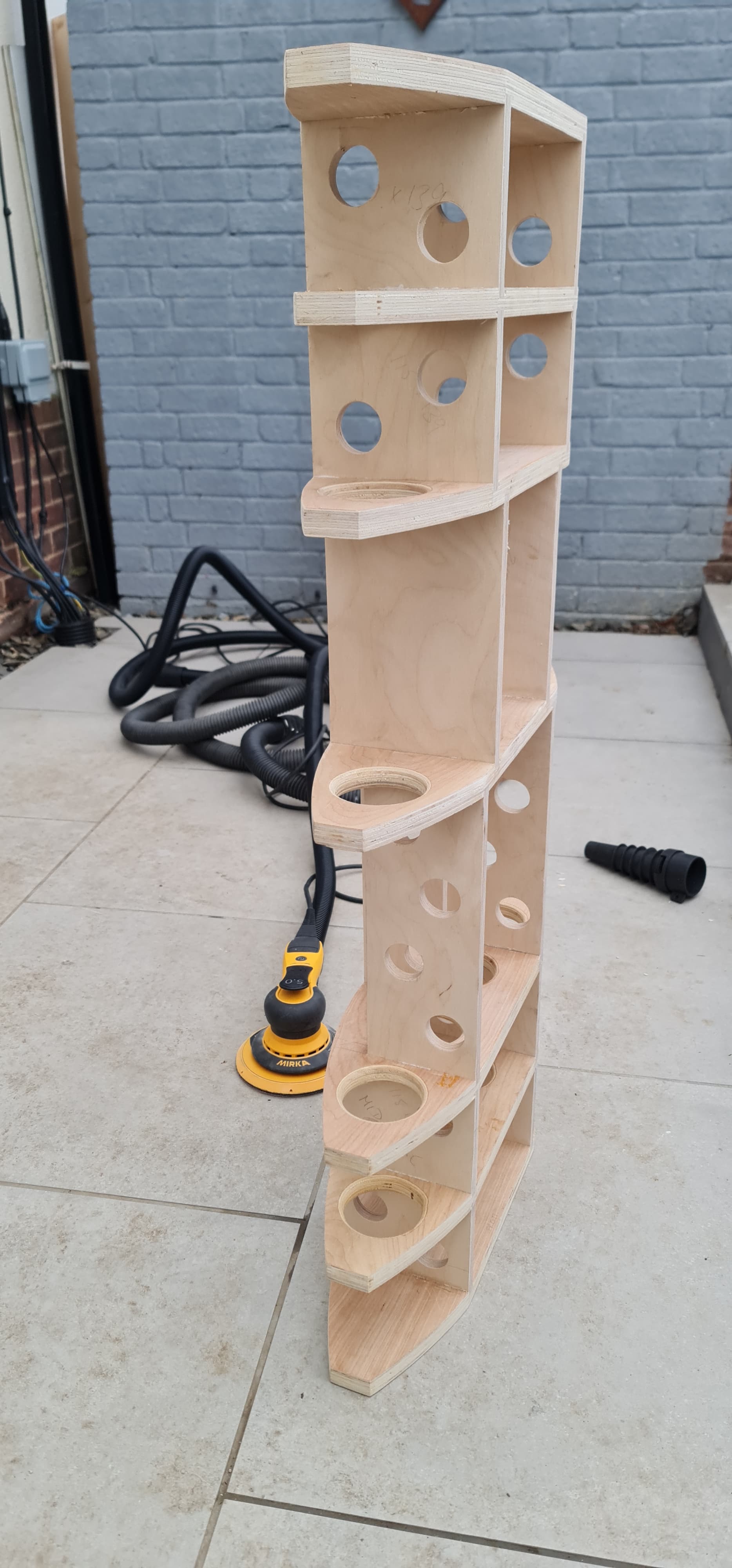
The cabinet is somewhat complicated, especially since I decided to go with kerf-bent curved plywood and a constrained layer damping system utlising 2 layers of 12mm Baltic birch sandwiched either side of a layer of Dodo Mat MLV (mass loaded vinyl). The cabinet will be wrapped in a 2/2 twill 3k carbon fibre weave, top and bottom panels will be 304 SS and the plinth will also be 304 SS.
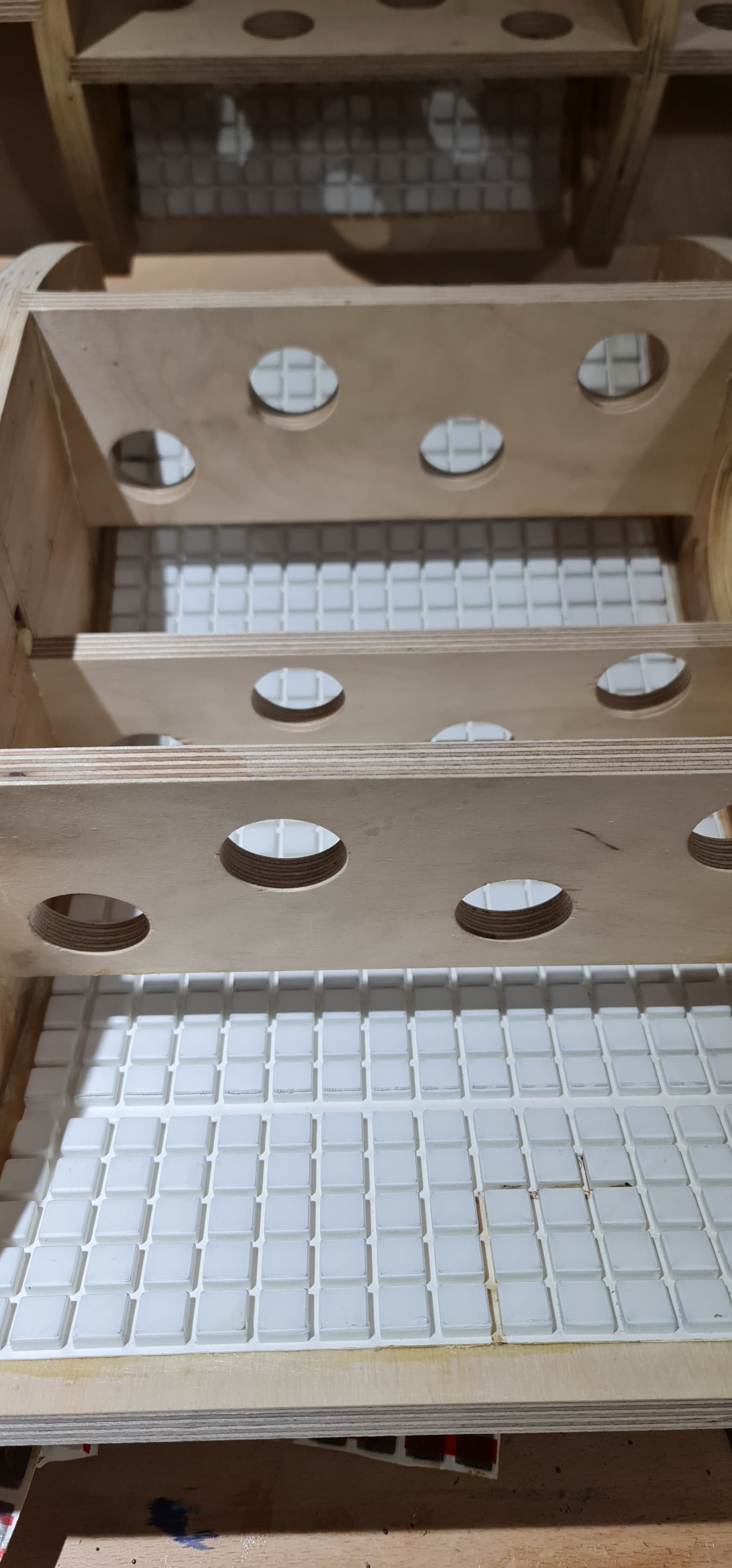
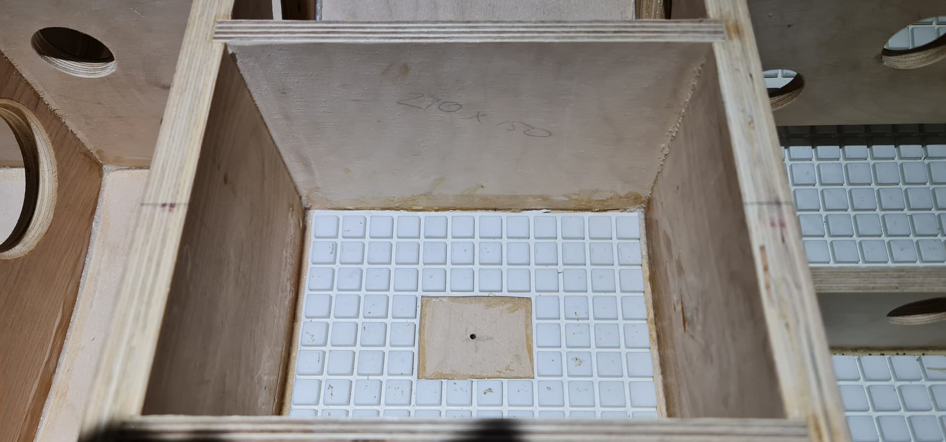
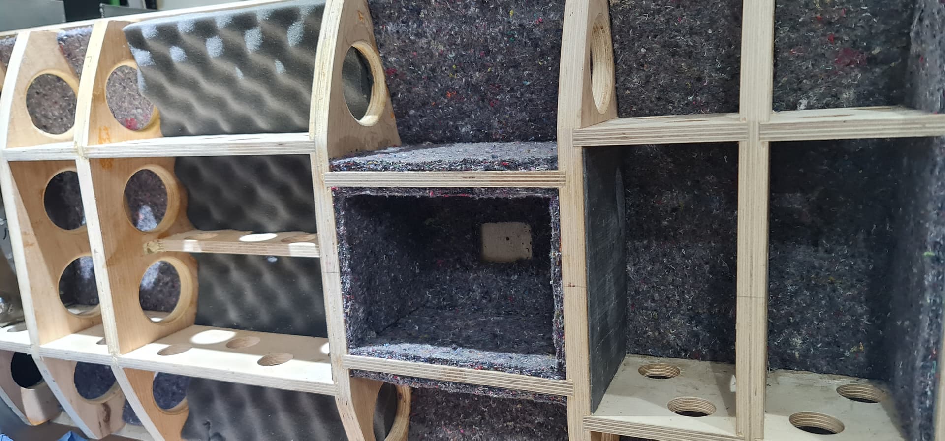
Cabinet skeletons:

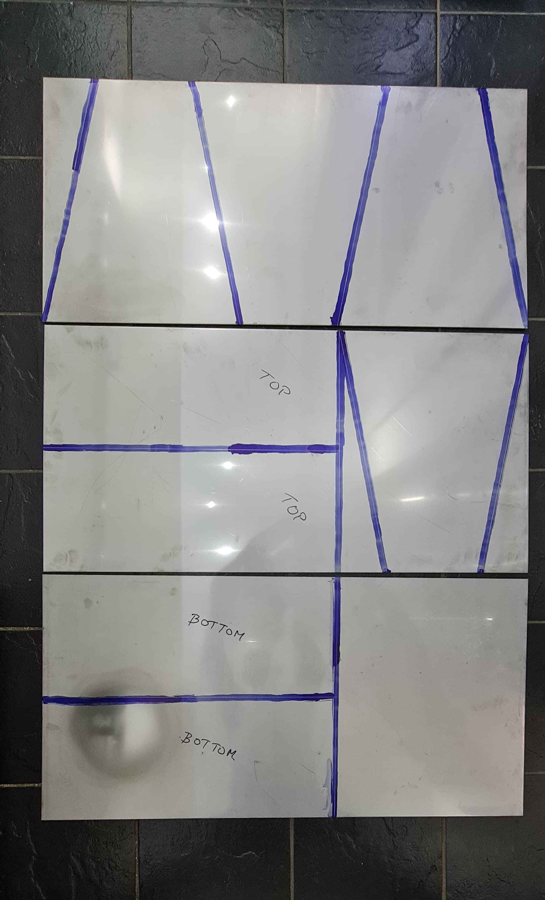
Stainless plate ready for plasma cutting:

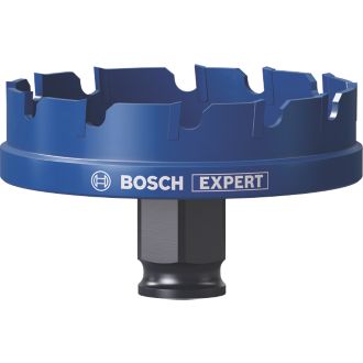
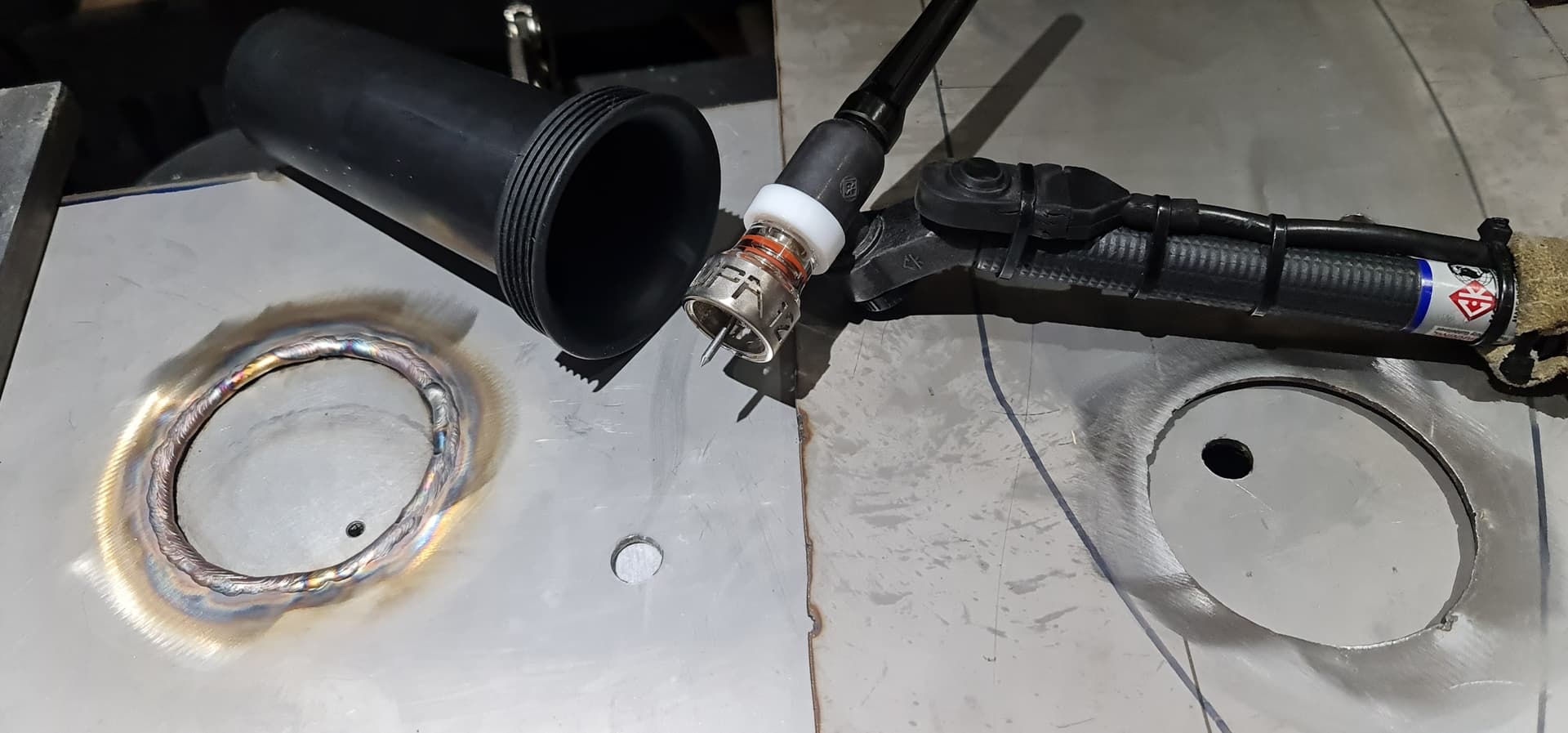
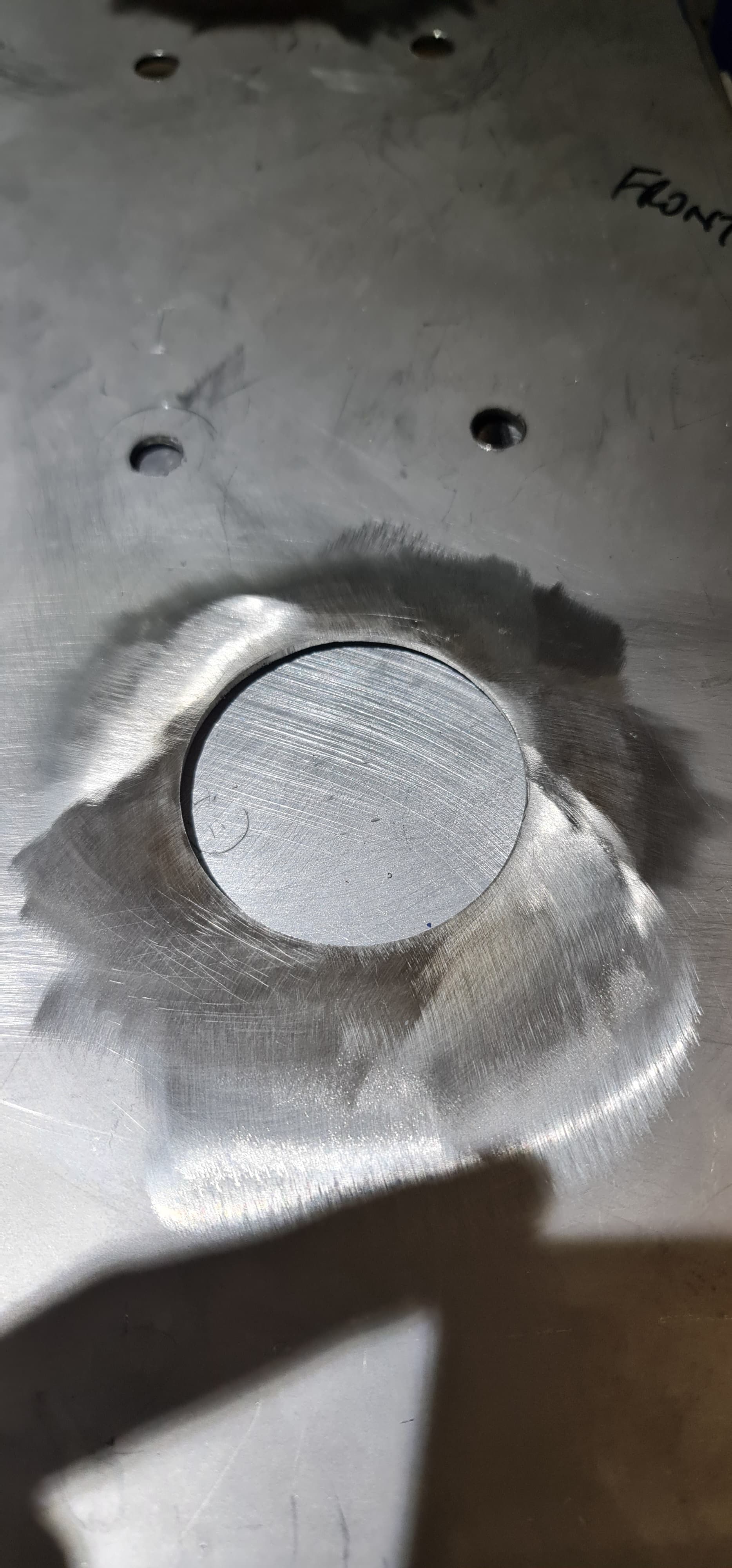
The cabinets are bottom-ported and despite my measurements, the smallest hole I could cut with my plasma cutter’s circle jig was a little oversized. In hind sight, I should have just bought the necessary 68mm carbide holesaw:

947RR_P

Instead, I had to reduce the size of the holes by TIG welding around them over a chunk of aluminium backer, followed by grinding and finishing:

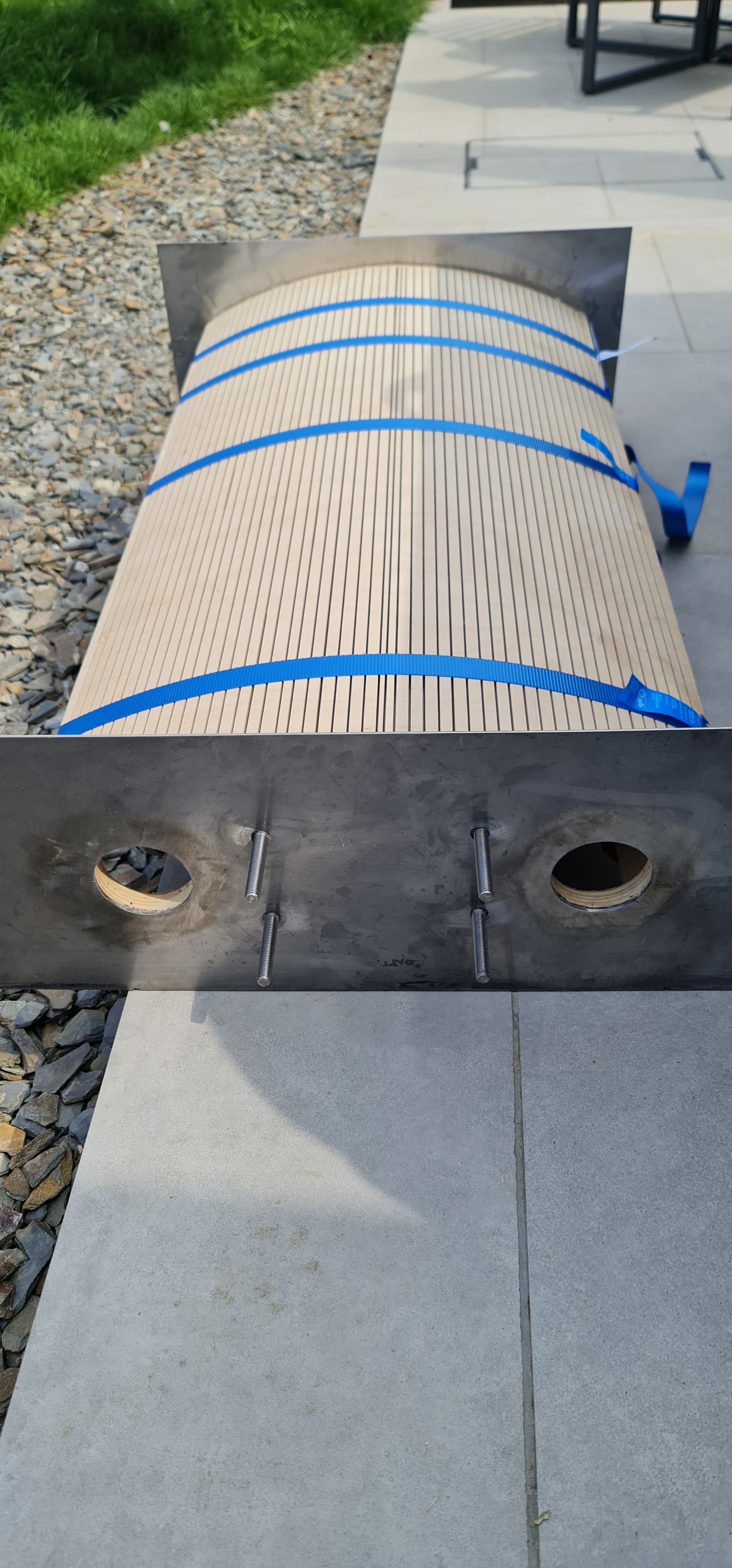
An inner plate with M10 304 studs welded to it provides the means of attaching the plinths:

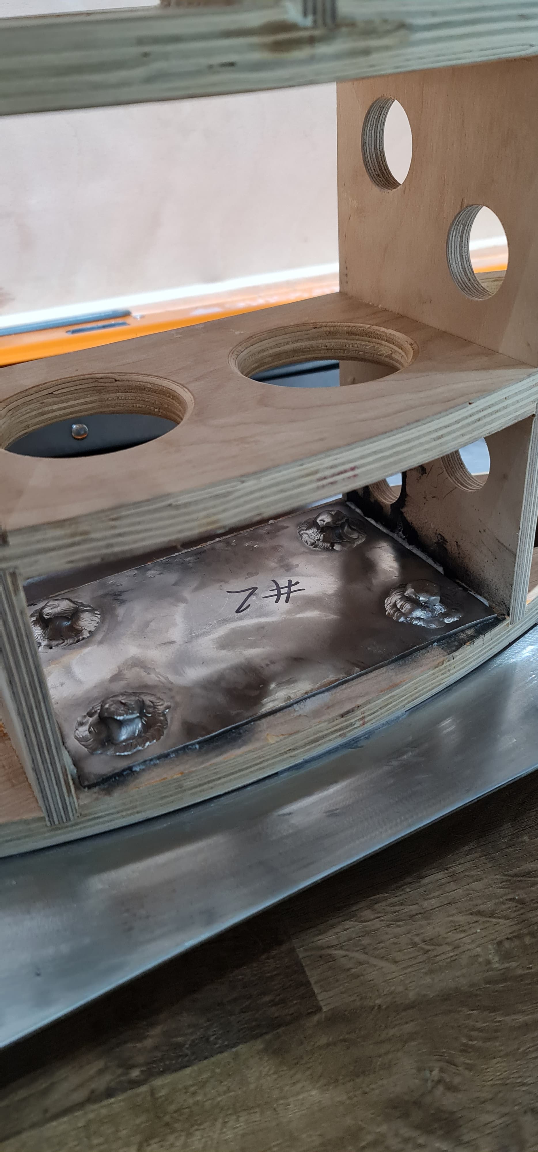
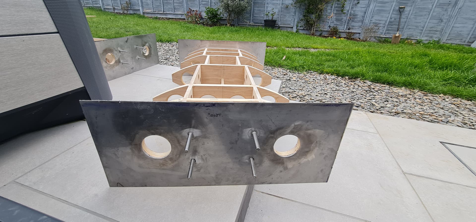
The top plate is bolted in place with M8 studs welded to it:

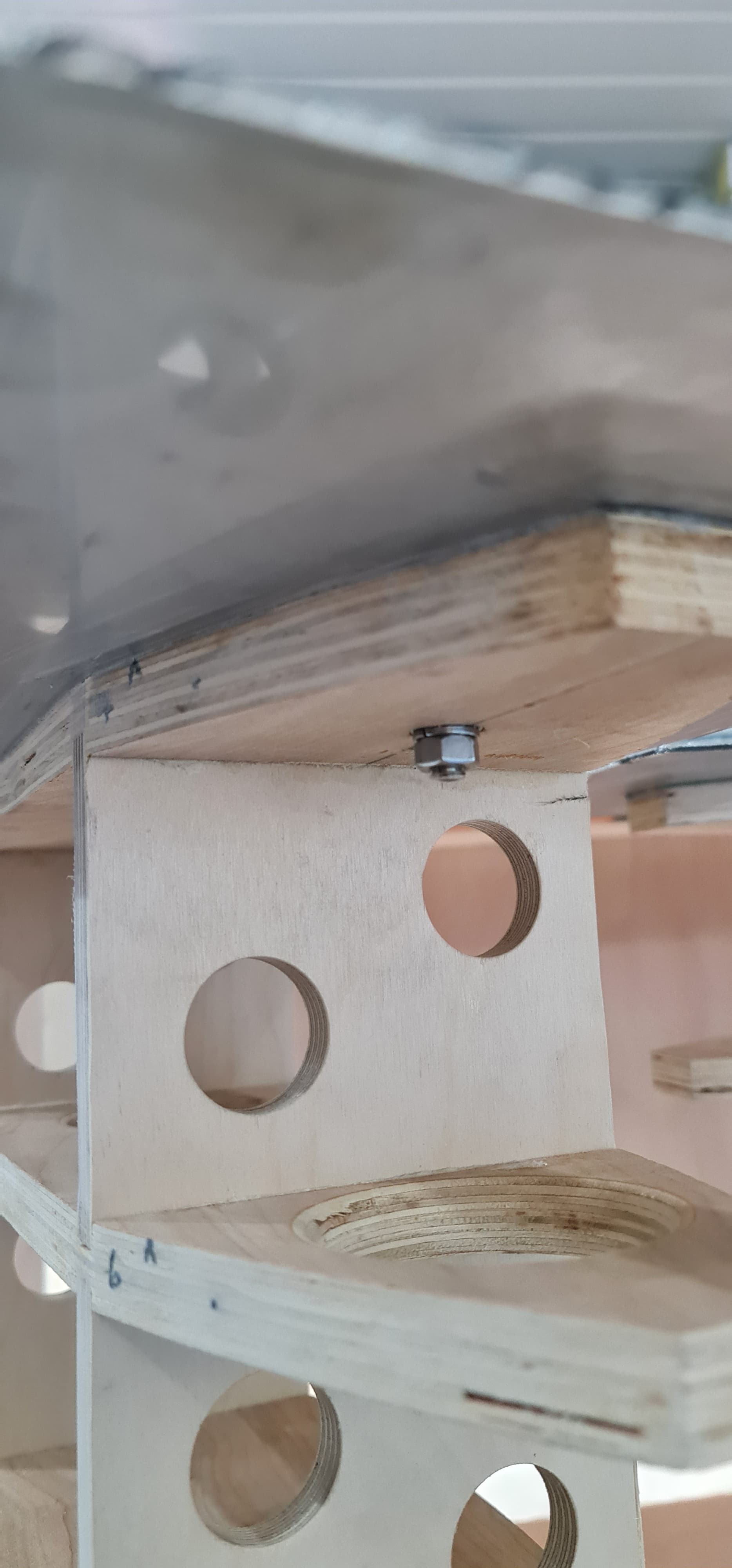
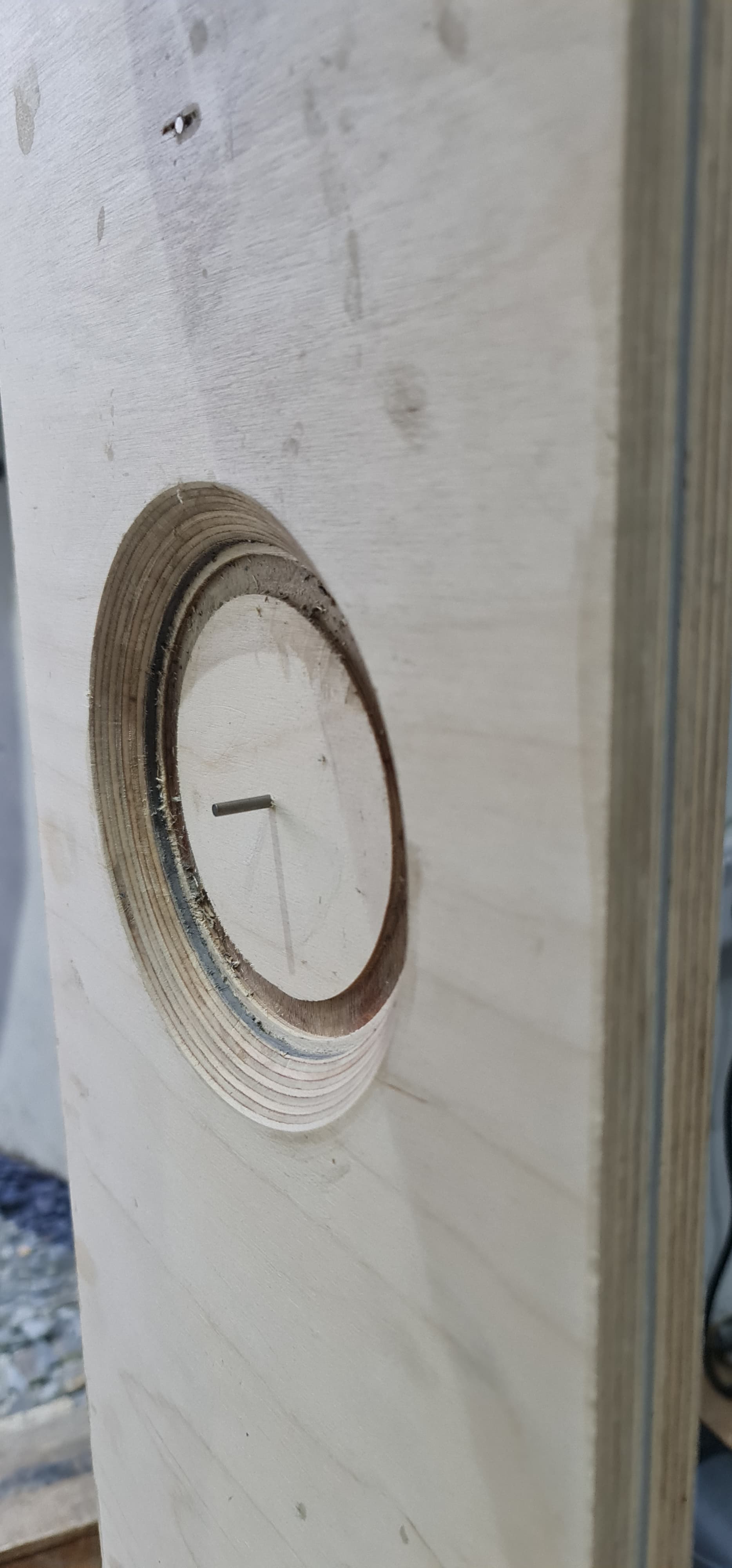
Midrange driver rear chamfer:

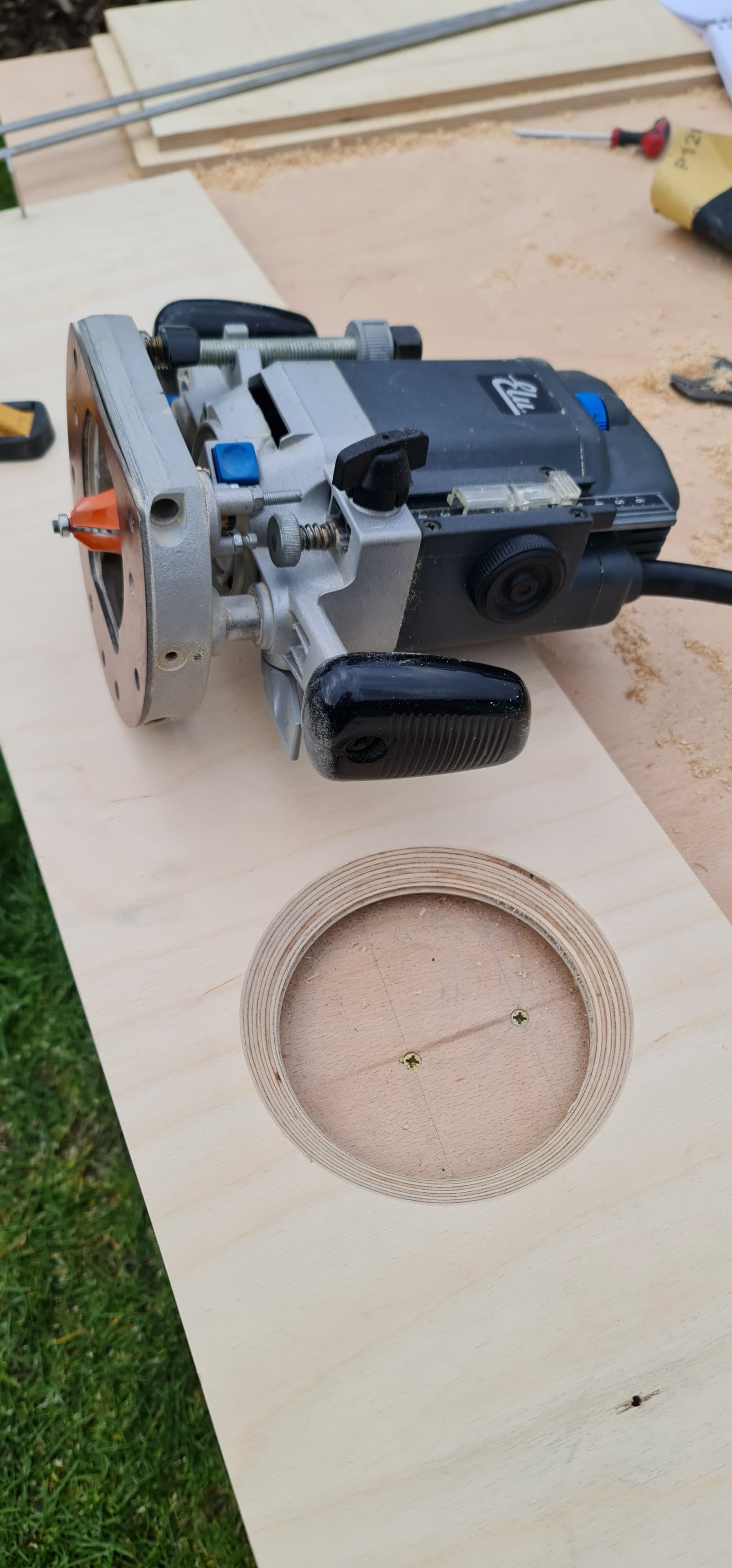
Sandwiched onto front panel with guide pin for routing the cutout after the carbon fibre is installed:

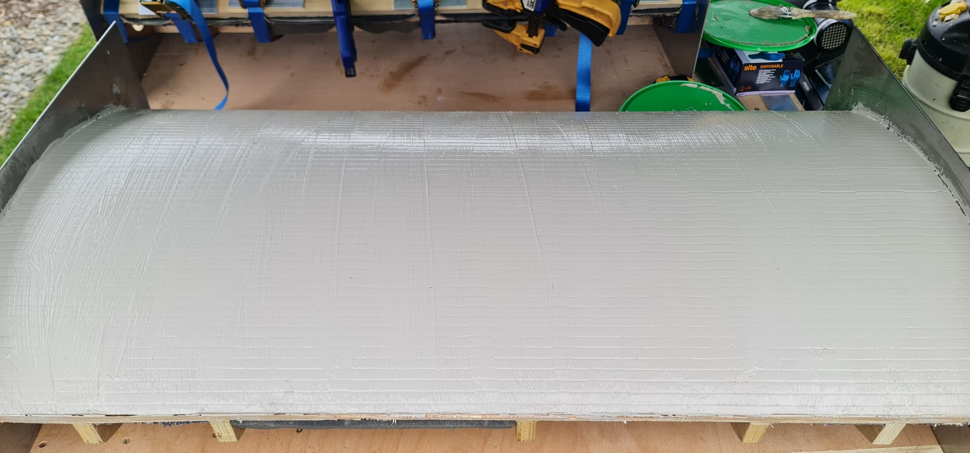
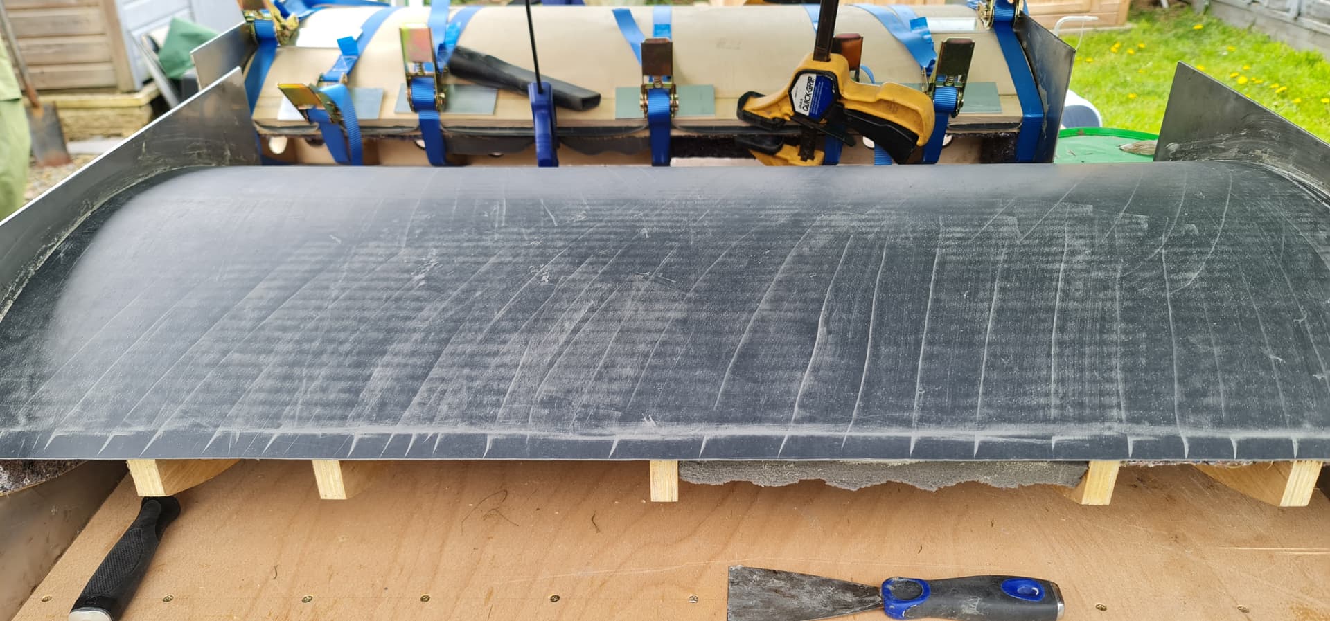
Constrained layer of Dodo Mat MLV sandwiched between layers of birch plywood:

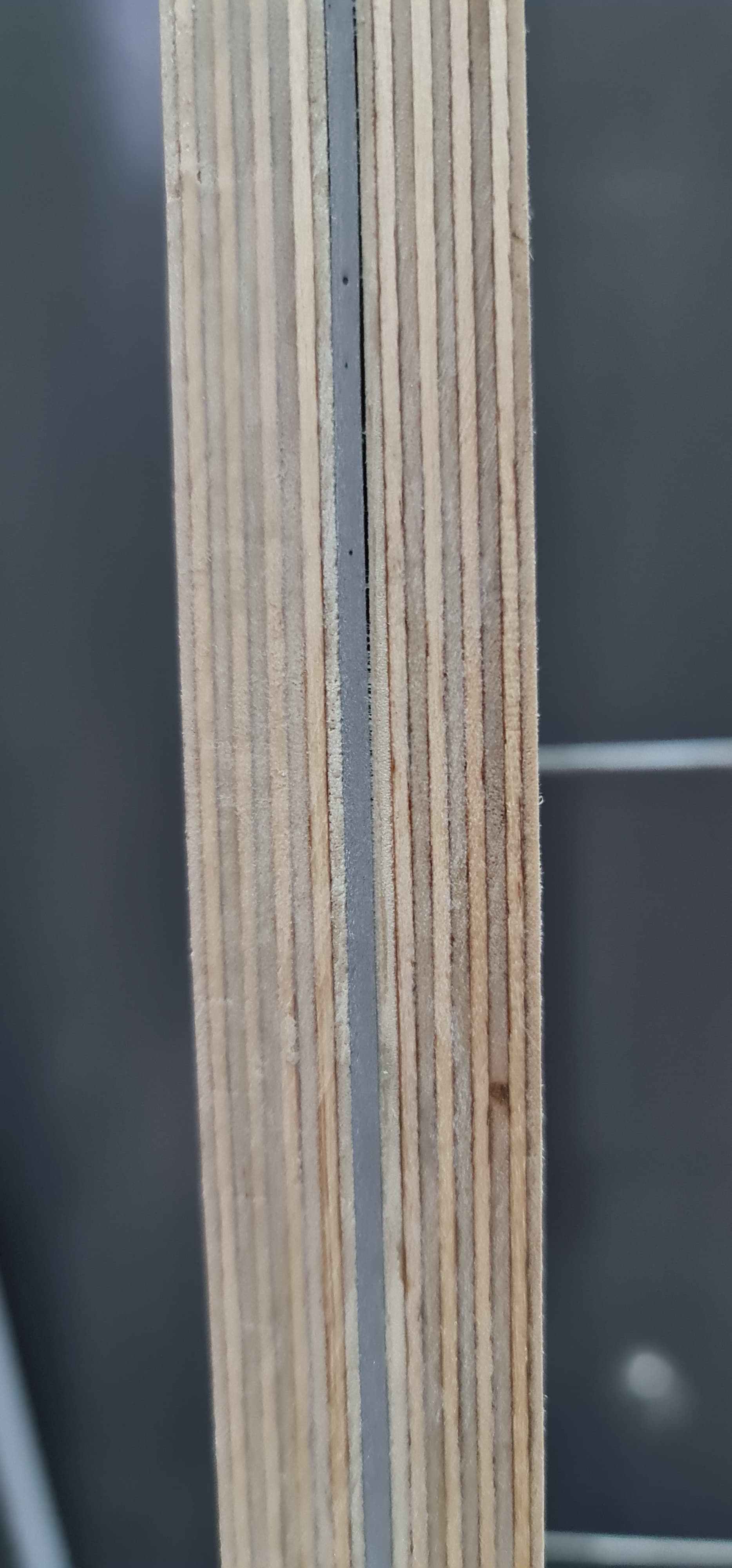
Adhesive used to bond MLV to plywood:

It sets to a rubbery solid, which is perfect for reducing resonances.

14 Likes

Kerf cutting the Baltic birch with a track saw:

First layer of kerf-bent ply glued on under the watchful eye of my apprentice:

Adhesive applied:

Dodo Mat laid on top of adhesive and air/excess scraped out:

Outer kerf-bent layer glued on and strapped in place:

16 Likes

Impressive. Huge amount of skill and coordination, planning and research. I bet is waaaay beyond rewarding to do it.
Can’t wait to see the final setup and thanks for posting all the process.

1 Like

great job! but your “apprentice” is the killer here! :joy:

1 Like

Around the bass driver and the midrange driver, I’m using Korff Hawaphon to damp the cabinet panels. Eggcrate foam added to the bass and felt added to the midrange.

The rest of the panels are damped with Dodo MLV and 8 mm felt.

I have another sheet of Hawaphon on the way from Germany to dampen the front panel of the enclosure.

The clear space with the drill hole is where the midrange driver’s port will be fitted.

Crossovers are mounted and wired up:

Need to do a little testing to make sure they’re wired up properly. Once they’re installed, I’ll have very limited access to them.

Sketches and scribblings for the plinths:

Plinths will be hollow, ~ 1/2 inch thick, and filled with steel shot.

I’ve made up the front panel on the first cabinet, so that I can add the dampening material to it. Still lots of bits to add. Cabinet is up to 42 kg. Seems my original estimate of 50 kg for cabinet plus plinth was a little shy… Getting a proper workout every time I move them around.

11 Likes

Sadly I have no :heart: to give out, but as always Graeme an Amazing amount of detail provided.

I am also looking forward the next phases of this project.

1 Like

took care of it for you…

2 Likes

Thanks I got some back this morning so was able to appreciate the posts with a bit of :heart:

1 Like

Will you be using the standard Stradivari drivers?

No, the Stradivari bass drivers are custom aluminium/magnesium 12" drivers made for Sonus Faber by Seas. The midrange is an Audio Technology paper cone and the tweeter is a custom modified Scan-Speak silk ring radiator.

The drivers in mine are 8" coated paper bass (SEAS CA22RNX), 6" coated paper midrange (SEAS MCA15RCY), and the cheap, but very good 27 mm SEAS 27TFFC silk-domed tweeter. This tweeter has been used in speaker designs from the likes of ProAc and Spendor.

There’s a version with the SEAS Excel magnesium drivers, but efficiency is 3dB lower due to the additional components needed to manage the magnesium midrange driver’s cone break-up.

4 Likes

While it was tipping down the other day, and before I’d given my fold-up gazebo a hefty coating of fabsil to restore its waterproofing (I can do a lot of stuff in the man cave, but draw the line at routing, as it’s still very messy even with dust extraction), I passed the time by making up my speaker cables.

Canare 4S11 Starquad and Neutrik Speakon connectors. I had originally planned to use the shiny metal NLT4FX connectors:

657-NLT4FX

These are solder termination only and the Canare’s polyethylene inner insulation wasn’t coping well with the heat needed to solder ~4mm² of stranded copper into the sizeable lump of metal in the connector, so I ended up going back to the trusty screw-terminal equipped NL4FC:

The visually astute will notice that the cable on the right is shorter than the one on the left. My amps are much nearer one speaker than the other.

I can almost hear the cries of “Heretic!” from the die-hards as they throw their arms up in horror :scream:

One is 3.8 m long, the other is 2.4 m long. When wired in pairs, the 4S11’s 4.3 mm² cross section delivers a resistance of 0.009 Ω per metre, so 0.0342 Ω and 0.0216 Ω respectively. Inductance, due to the cable geometry is vanishingly small at 0.5 uH and 0.3 uH.

Capacitance is also very low:

Inductive reactances at 20 kHz (worst case) are 0.06 Ω and 0.04 Ω.

Parallel capacitive reactances, also at worst case of 20 kHz are 14.8 kΩ and 25 kΩ

Compared to an 8 Ω nominal speaker impedance, the effect of different cable lengths is phenomenally small and absolutely inaudible! Dontcha just love science? :rofl:

7 Likes

I have read that it affects timing of the signal to the speakers… This has never made sense to me as the difference in time between the electrical signal traveling from amp to speaker is dwarfed by the time from speaker to ear. And would be dominated by the most minute difference in distance between your noggin and the left and right speaker.

I can believe that differences in resistance, inductance, capacitance could have an effect… but I’ve not researched this, or tested my cables.

My AZ listening room has mismatched speaker wire lengths that cannot be easily solved. I expect that any lossage related to that is rendered undetectable by larger things, like the acoustics of my room.

2 Likes

Just shows we really can’t trust everything we read.

Electrical signal propagates along a wire at somewhere close to the speed of light.

The difference in cable length here equates to a propagation delay of around 5 nanoseconds - That’s one hundred thousandth of the minimum sound delay detectable by a human (half a millisecond)!

In theory, yes, but they would have to be huge differences. In reality, the effect of speaker cables gets lost compared to the tolerances of components in a passive crossover. They’re several orders of magnitude lower.

A typical bass driver inductor will be a few milliHenries. A really tight tolerance inductor is +/- 1%, typical is ~5%. 1% of 3 milliHenries is 30 microHenries, a hundred times more than the inductance of the shorter of my two cables.

The capacitance comparisons are similar orders of magnitude apart.

As you said, there are much bigger things to be concerned about!

6 Likes

That looks like a very nice speaker. Also a good choice. The mid fits well with the woofer, you don’t even need a resistor in series that could spoil the damping factor from the amp. I guess this will sound like an active speaker, you should be able to play loud without hurting your ears when a good amp controls the driver directly connected to it (without resistance). Like in the good old days.
If I were you I would use the 4 pins of the Speakon connector for low, mid, high and ground to mount the x-overs outboard. There is no such fun as to tweak the x-overs.
I would ask Troels to send the computermodel of the design, so you can change values and see for yourself what happens, and then listen to the result. He designs a lot of speakers so there is always room for adjustments.
Troels wrote that his cd’s never sounded better than on the Yamaha NS-1000. I have those speakers and found out that even these ones really can sound better. Just a little tweak in the x-over does more to the sound than any cable can.

2 Likes

Now you’ve got me thinking… :thinking:

Rebuild a pair of Bang Olufsen speaker with a Hifiberry digital amp.


1 Like

I considered a pair of those for our gym room, however, I will soon have a spare pair of ZaphAudio ZRTs…

Fantastic post, can’t wait to see the progress. I’ve always thought about building my own speakers and this account of how-to has convinced me – I’ll just purchase future speakers!

2 Likes

Be aware that many d class and other amp types might not have a common ground…if you really want external covers I would use a speakon that supports 4 pairs of connections like the one I used here in the middle of the panel

Thanks. It would work with a 4 core cable from the xover to the speaker though. Mid and Tweeter + and bass - are common. Bass +, mid - and tweeter - could then use the other 3 cores. It’s a parallel crossover, so no issues.

If I miss-wire anything, the AHB2s will just shut down.

That said, I’d probably still rather do it right and utilise the cables as they were intended - if they’ll fit into the connector.

Or I could use 3 x 2 pole Speakons…

2 Likes